Created a circuit that turns on an LED light when a button is pressed and also a circuit that does the
opposite and turns off the LED when that same button is pressed.
Materials Used:
Power Supply Module
Button
830 Tie-Points Breadboard
Breadboard Jumper Wire
9V Battery with Snap-on Connector Clip
100 Ω Resistor
LEDs
Multimeter
Procedure:
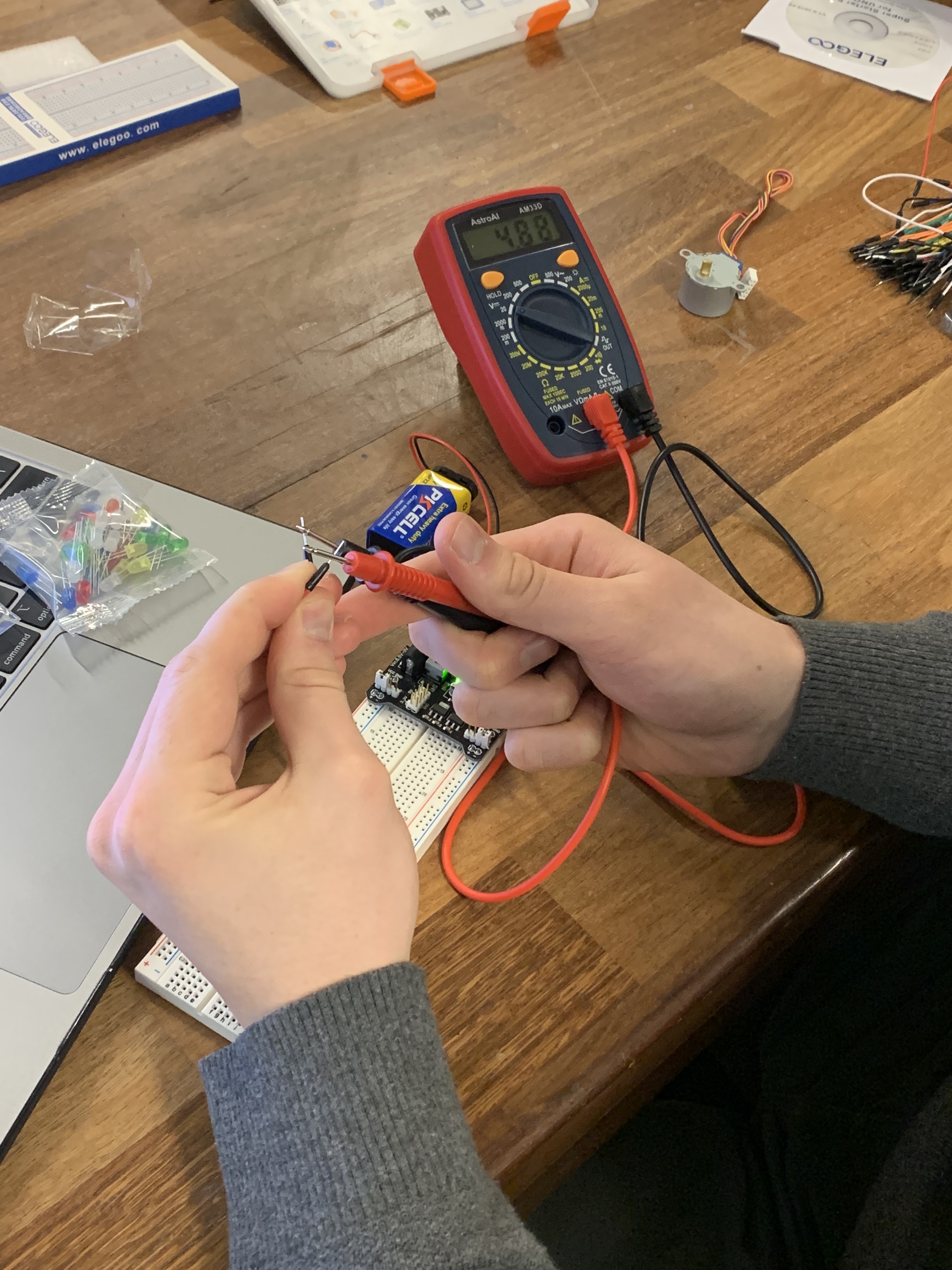
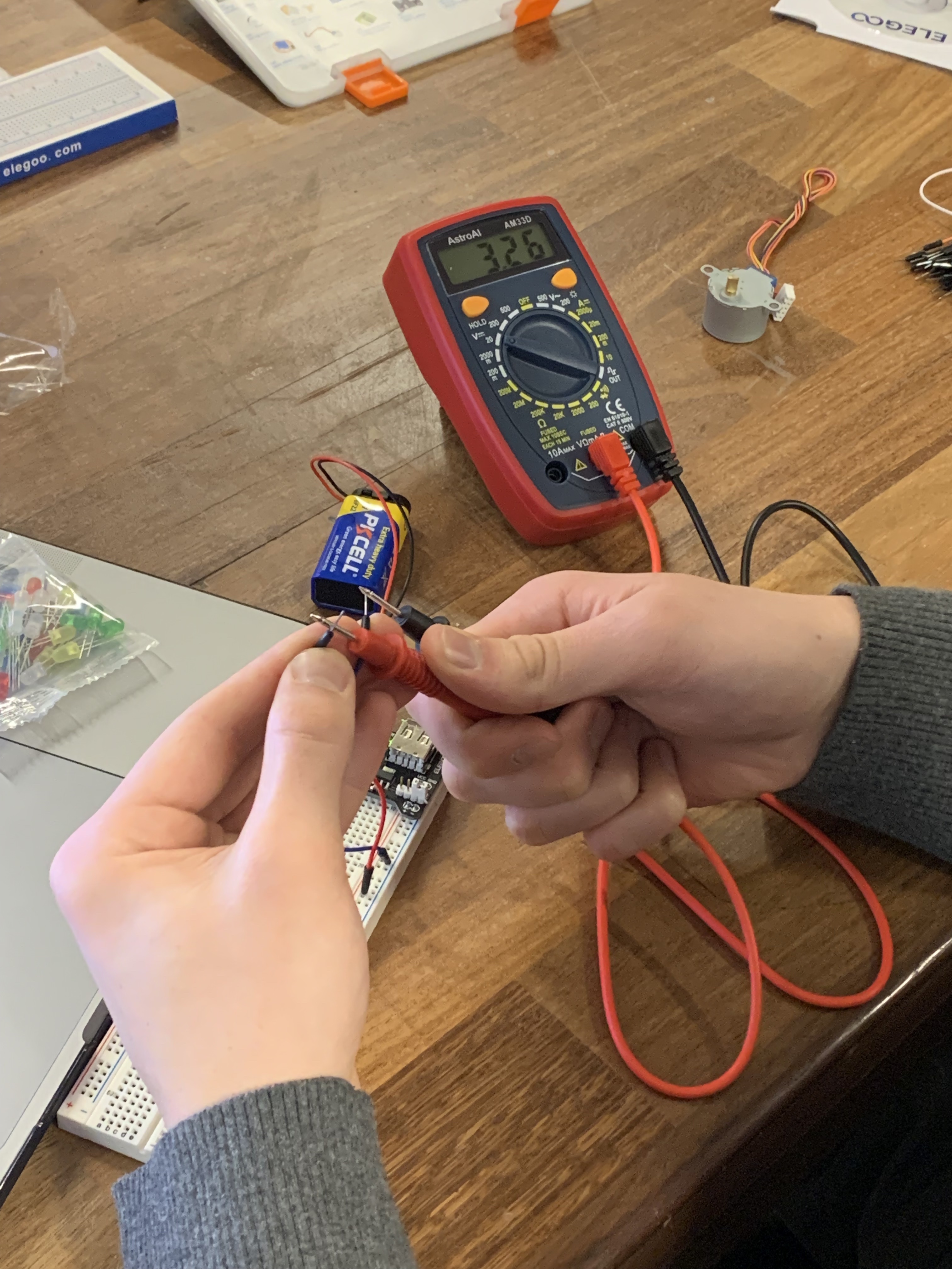
Set up power
Tested Expected Voltage
Hooked up wiring for LED without button
Included button to complete the circut and turn on the LED when pressed
Rewired the button to break the circut and turn off the LED when pressed
Testing 5V Breadboard
Testing 3.3V Breadboard
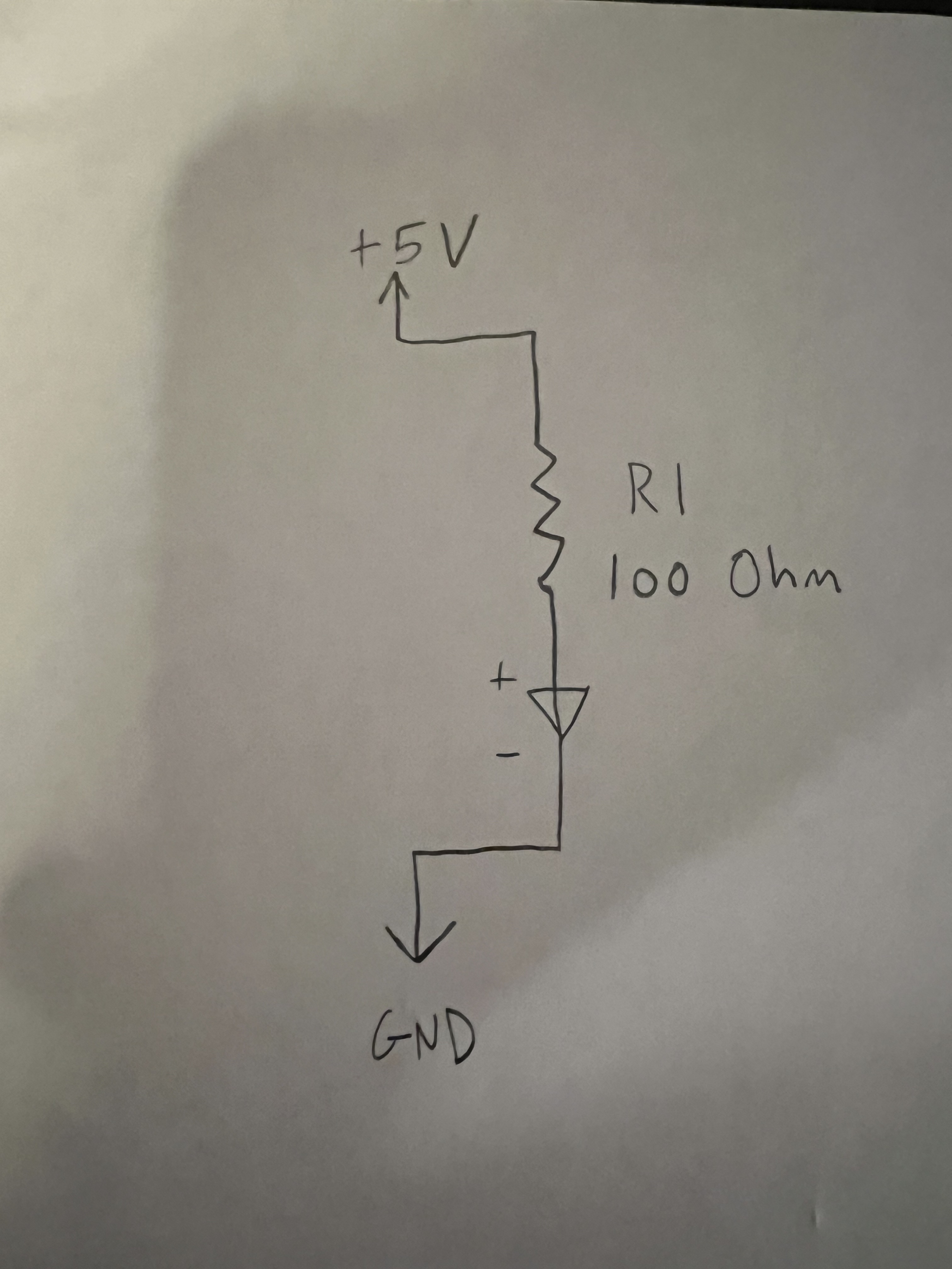
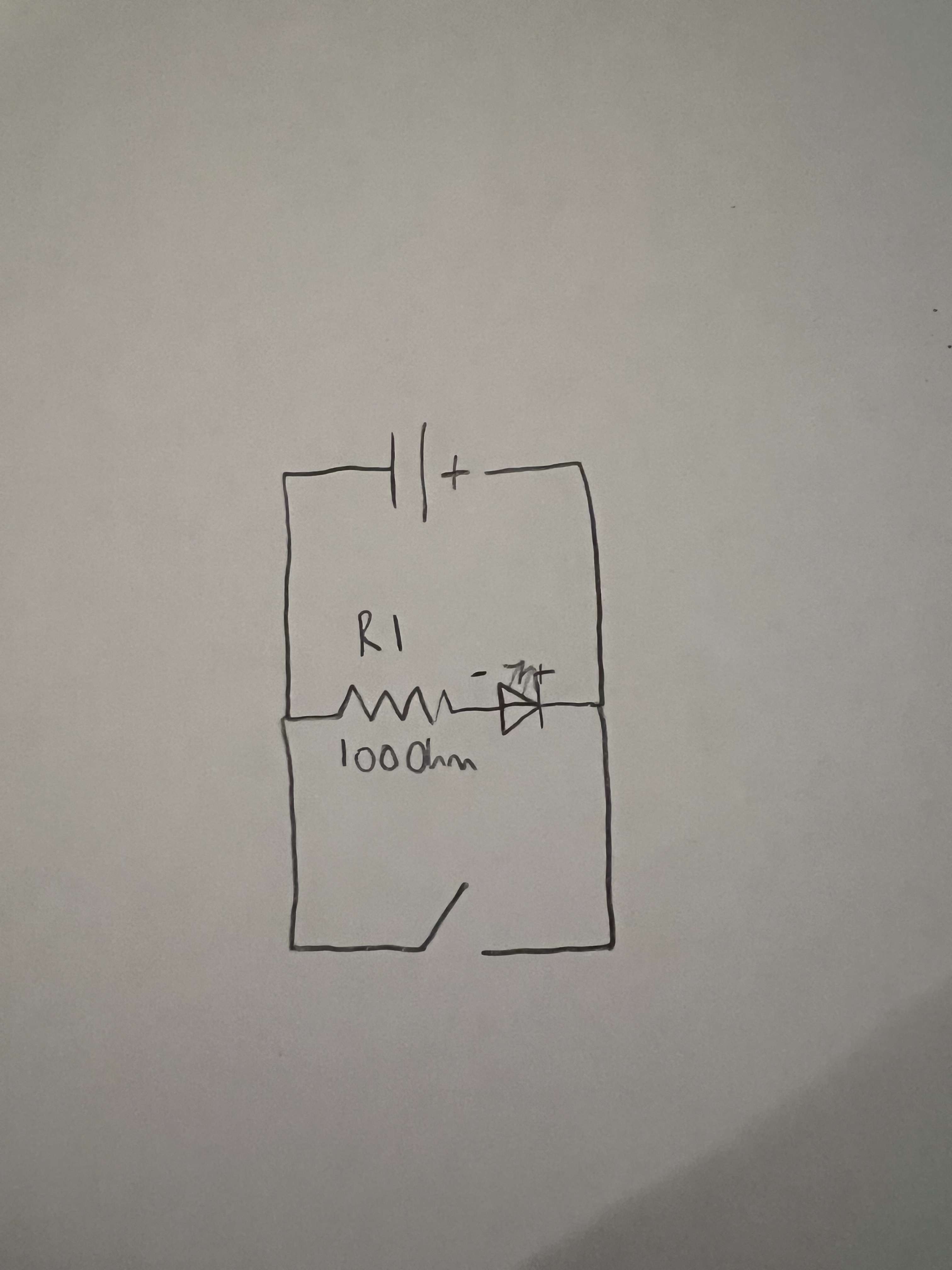
3.3V LED circuit
Ohm's Law Calculation for 5V LED circuit
V=I*R => R=V/I => R = 5 V / 50 mA = 166 Ω
5V Schematic
3.3V Circut with button to turn on LED
Schematic for 3.3V Circut with button to turn on LED
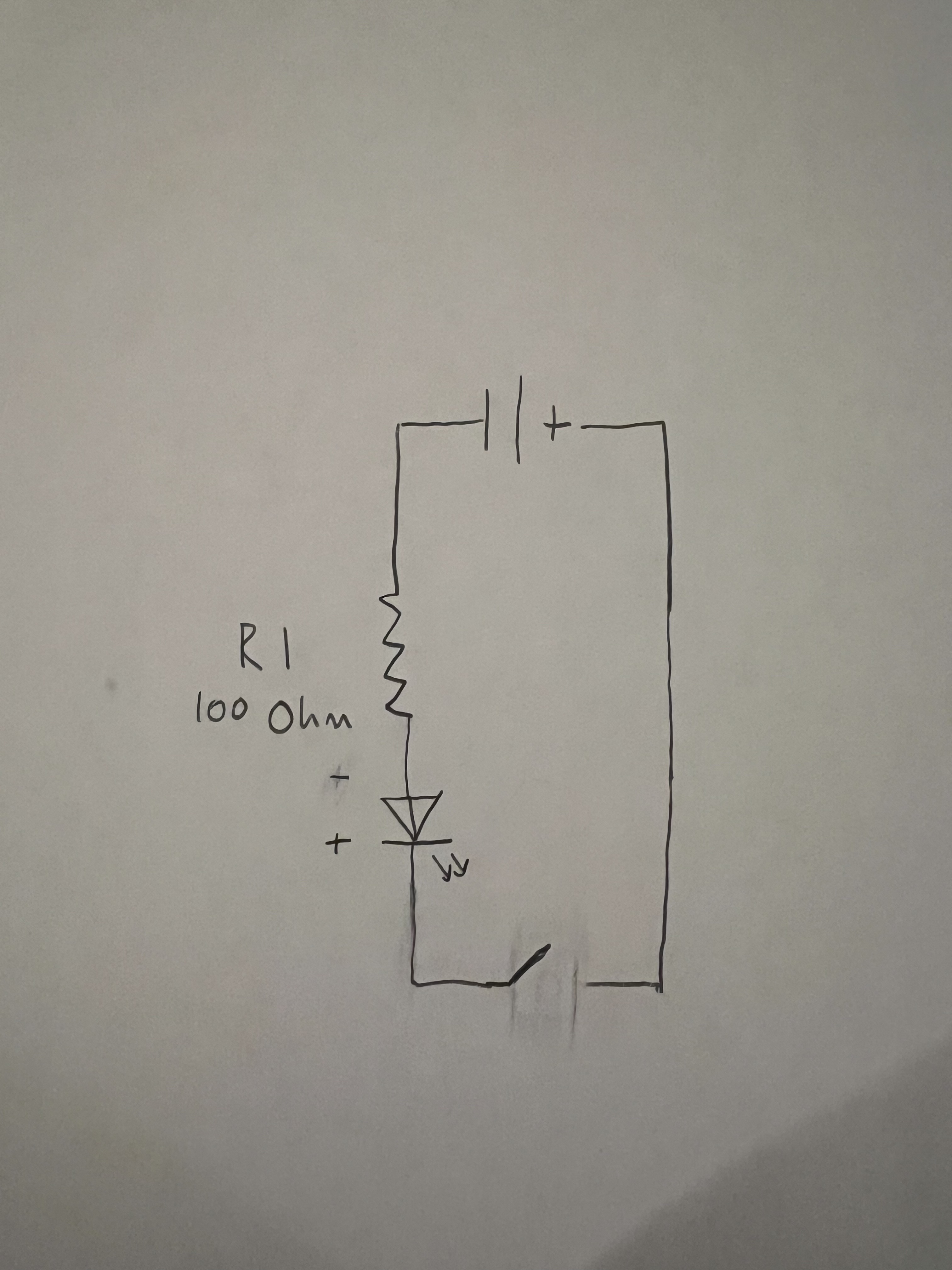
Extra Volt
Extra Volt Schematic
Lab 2
Description:
This lab is an introduction to the Arduino, its Integrated Development Environment (IDE), and digital I/O on the Arduino.
We set up the workflow of programming an Arduino and learn about how to manipulate and sense it's digital pins.
Over a series of steps, we will build an LED reaction game to test who has the fastest reflexes!
Materials Used:
Arduino (Elegoo) Uno R3 Controller Board
USB Cable
USB Adapter
Button
830 Tie-Points Breadboard
Breadboard Jumper Wire
Resistors
LEDs
Multimeter
PART 1: SETTING UP THE ARDUINO IDE
Procedure:
Install the Arduino Integrated Development Environment (IDE)
Navigate to File > Examples > 01. Basics > Blink and click to open the Blink example in a new window
Upload this code to the board by clicking on the arrow button on the toolbar
Wait for the "Done Uploading" message
Watch the LED on the Arduino Board blink repeatedly
Blinking LED on the Arduino board
Problems Faced and Conclusion:
There were no problems for this section of the lab and the LED on the arduino board blinked successfully
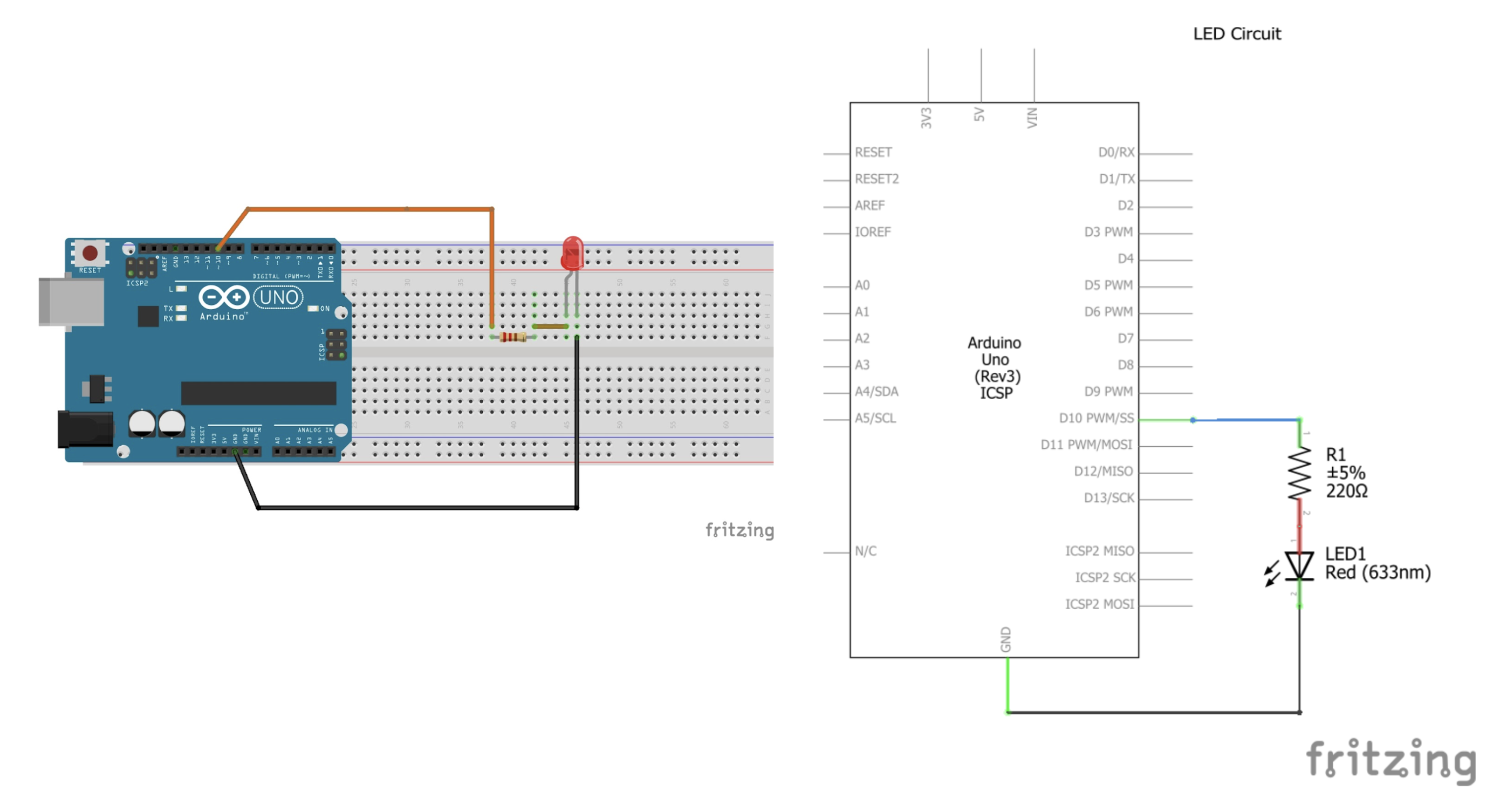
PART 2: BLINKING AN EXTERNAL LED
Procedure:
Wire the Arduino and breadboard in conjuction with the schematic provided
Use the Blink example from Part 1 as starter code
Declare a global variable equal to 10 outside of the setup() function and the loop() functional declarations: “int LED_PIN = 10;”
Replace LED_BUILTIN everywhere with our variables name:“int LED_PIN = 10;”
Upload this code to the board by clicking on the arrow button on the toolbar
Wait for the "Done Uploading" message
Watch the LED on the external LED blink repeatedly
LED + Arduino Uno circuit diagram and schematic
Code for blinking external LED with standard delay:
Video of blinking external LED with standard Delay
Code for blinking external LED with longer delay:
Notice that delay(1000) has been changed to delay(2000) on both lines 11 and 13
Video of blinking external LED with longer Delay
Problems Faced and Conclusion:
There were no problems for this section of the lab and the external LED blinked successfully
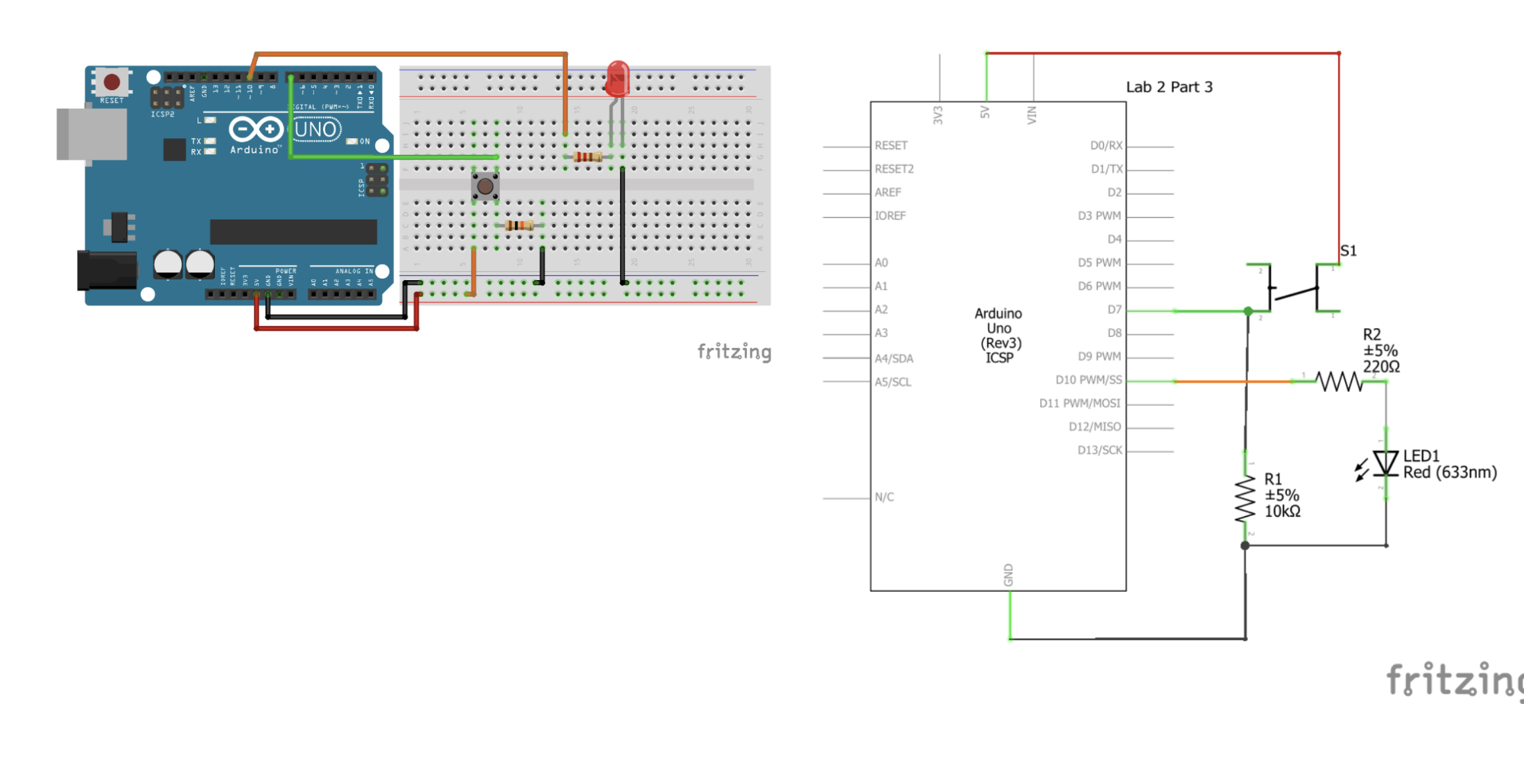
PART 3: BUTTON PRESS AND SERIAL MONITOR
Procedure:
Wire the Arduino and breadboard in conjuction with the schematic provided
Open a new Arduino sketch through File > New Sketch (or Ctrl+N)
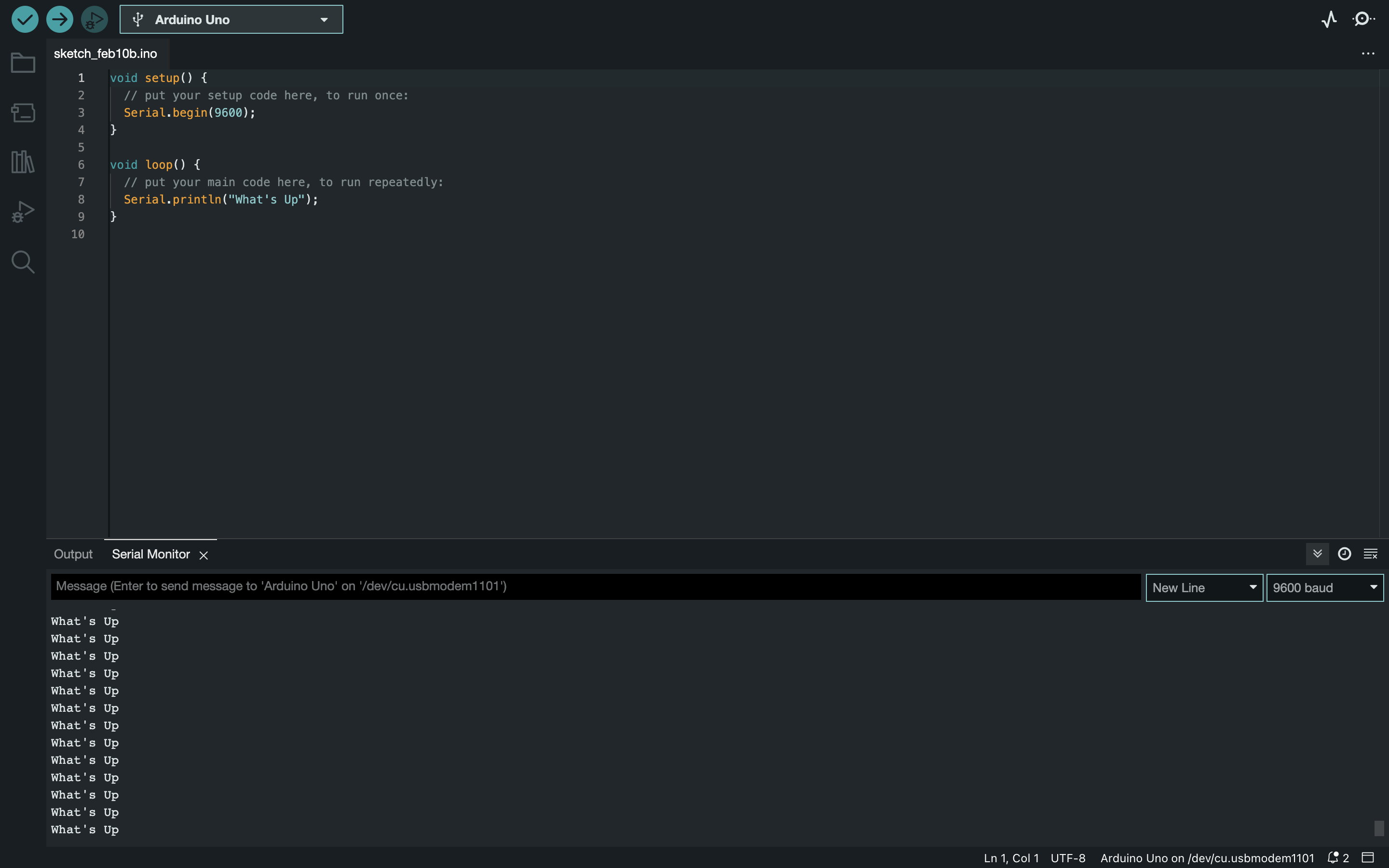
In the setup() function declaration, add a function call to Serial.begin(9600)
Inside of the loop() function declaration, call Serial.println("Hello, World")
Customize this message
Set up the pin as a digital input by calling the function pinMode(INPUT_PIN, INPUT) in the declaration of the setup() function
Using the digitalRead() function (which returns HIGH or LOW), a while() loop so the aduino prints a “waiting” message to indicate that it is
waiting for the button to be pressed and a “success” message as soon as the button is pressed going back to the "waiting" message after.
Illustration and schematic of button circuit
Code for Custom Message:
Output in console of custom message
Code for BUTTON PRESS AND SERIAL MONITOR change
Video of serial monitor working
Problems Faced and Conclusion:
Getting the code to work for this part of the lab was pretty dificult and I had to do extensive work with the TA Aarya to get it working. Also there was an issue with the Arduino IDE thowing a avrdude: stk500_recv(): programmer is not responding error when I used my USB adapter for my mac so I had to use a different USB adapter.
PART 4: LED REACTION GAME
Procedure:
Use the same Arduino and breadboard wiring as Part 3
Open a new Arduino sketch through File > New Sketch (or Ctrl+N)
We will design an LED Reaction game, where the LED connected to the Arduino will turn on
after a random time interval, and then the player will need to press the button as soon as they notice the LED.
The output of this game would be the time that the player took to press the button,
which can serve as a score to compare with other players.
In order to generate a random integer on Arduino, use the random() function
Use the randomSeed(seed); function with a seed value of your choice to ensure variation.
Use the millis() function to track time
Code for LED game
Video of LED Game working
Problems Faced and Conclusion:
There were no problems for this section of the lab other than trial and error. The LED game worked successfully.
Lab 3
Description:
In this lab we will learn how to solder! Soldering is a technique to connect two pieces of
metal together by melting another metal/alloy (Solder) between them. Solder has a much lower
melting point than the copper wires or components that we will connect with it. Soldering is a
very useful electrical prototyping skill.
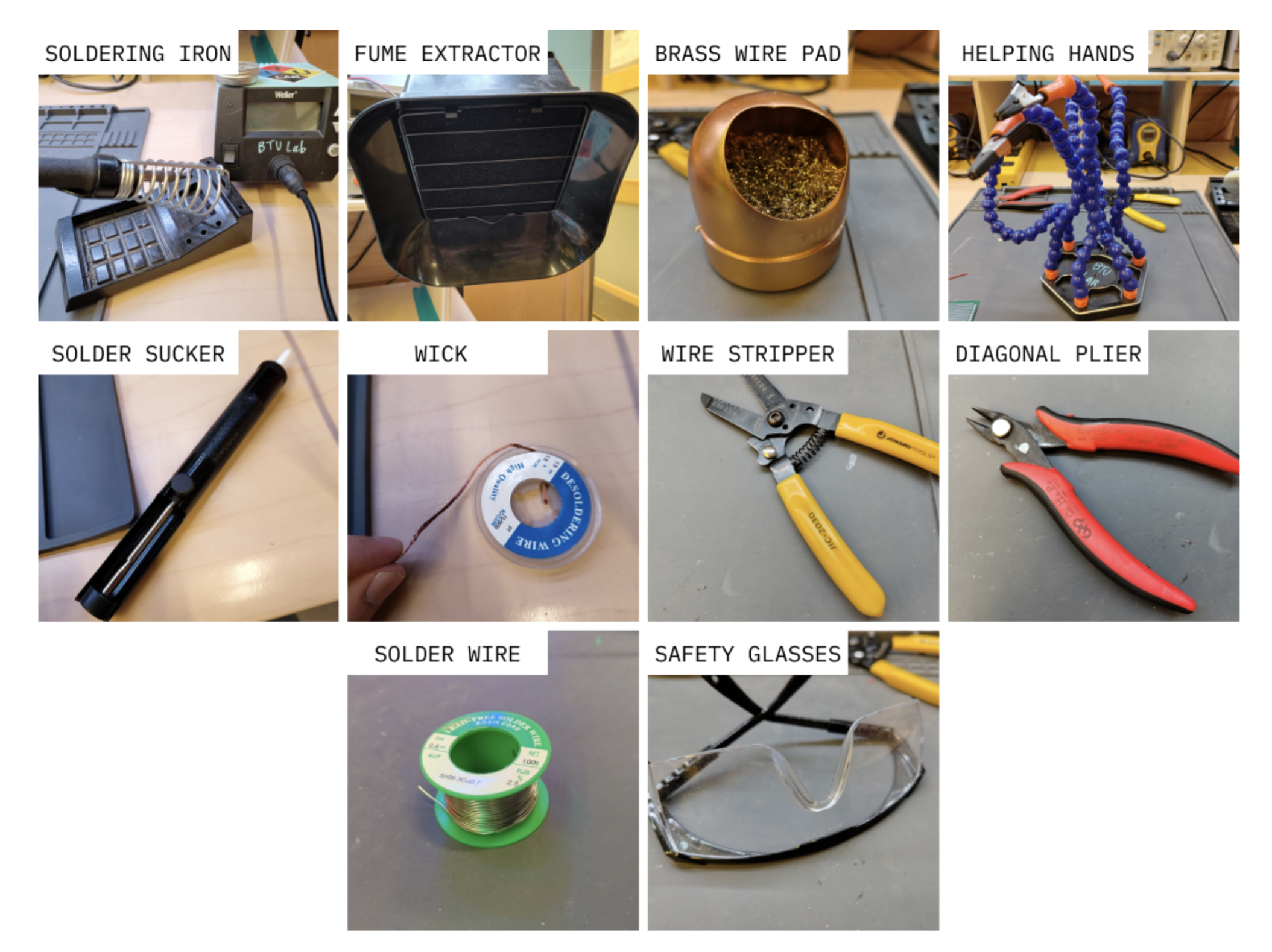
Materials Used:
Arduino (Elegoo) Uno R3 Controller Board
USB Cable
USB Adapter
Breadboard Jumper Wire
Resistors
LEDs
Multimeter
Protoboard
Stranded and Solid-core Wires
Soldering Iron
Solder Wire (Lead-free, rosin core)
Fume Extractor
Brass Wire Pad
Soldering Helping Hands
Solder Sucker Desoldering Pump
Solder Wick
Wire Stripper
Diagonal Pliers
Safety Glasses
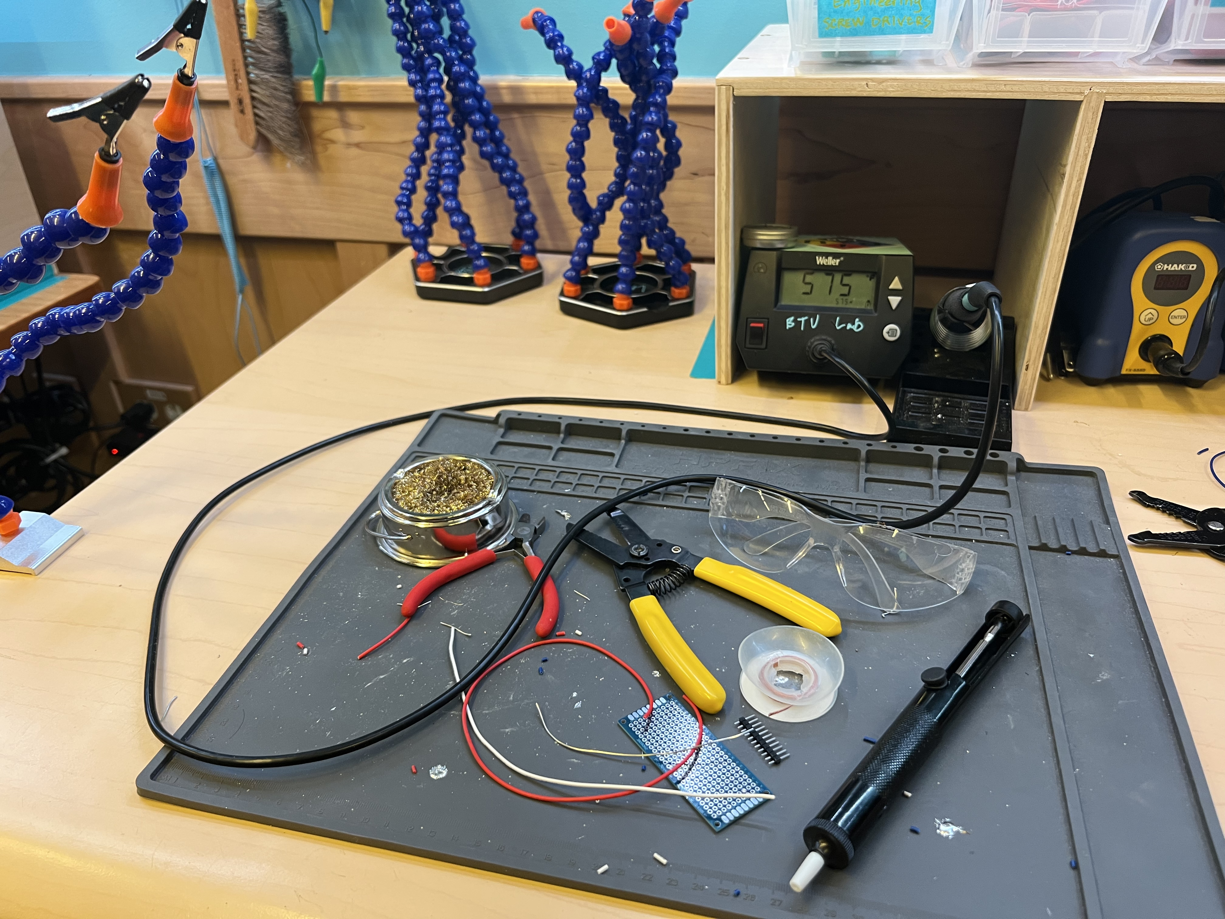
PART 1: SOLDERING SETUP AND SAFETY
Procedure:
Assemble all of the tools in the photo below
Set up the soldering station by turning the soldering iron ON using the switch
The appropriate temperature for soldering is between 600 ℉ - 700 ℉ (325 ℃ - 375 ℃),
so ensure that the number on the screen that represents the current temperature of
the iron is within this range.
Once the temperature is set, be very careful while handling the soldering iron. The tip
of the soldering iron is at the temperature displayed so always grab the soldering iron using the handle.
Never keep the soldering iron outside its stand; don’t put it directly on the table or on some other surface – it will burn through the material
Once the soldering iron is turned on, turn on the fume extractor fan. Solder contains harmful chemicals and metals (like lead), so it’s important to have some ventilation and filtration, which are provided by the fume extractor.
Always remember to wash your hands with soap and water after soldering
Do not eat or drink near the soldering station
Molten solder has a tendency to splatter, so you should always wear safety glasses while soldering to protect your eyes
Materials Required:
Materials Assembled
Problems Faced and Conclusion:
There were no problems faced with this section of the lab everything went smoothly.
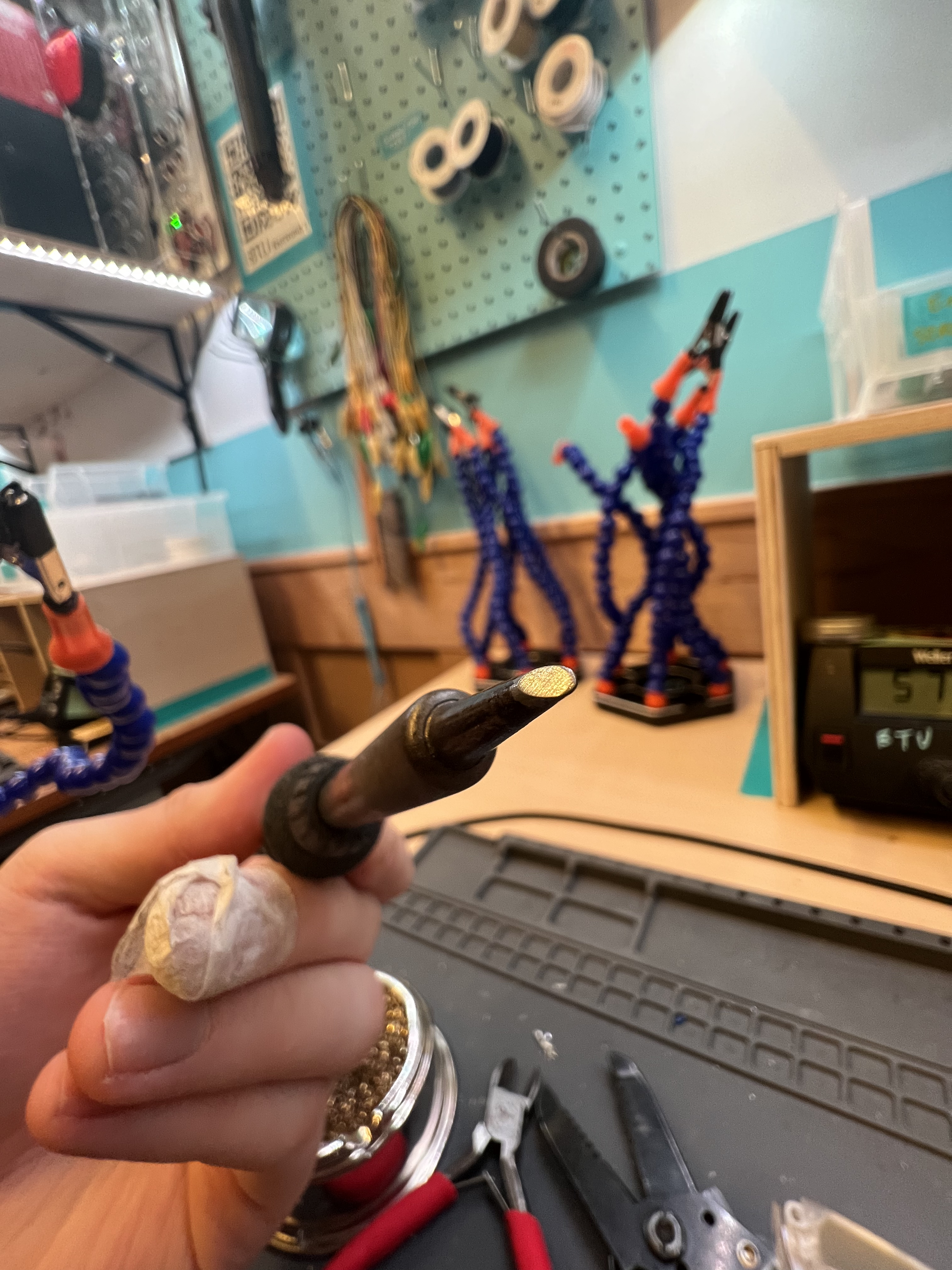
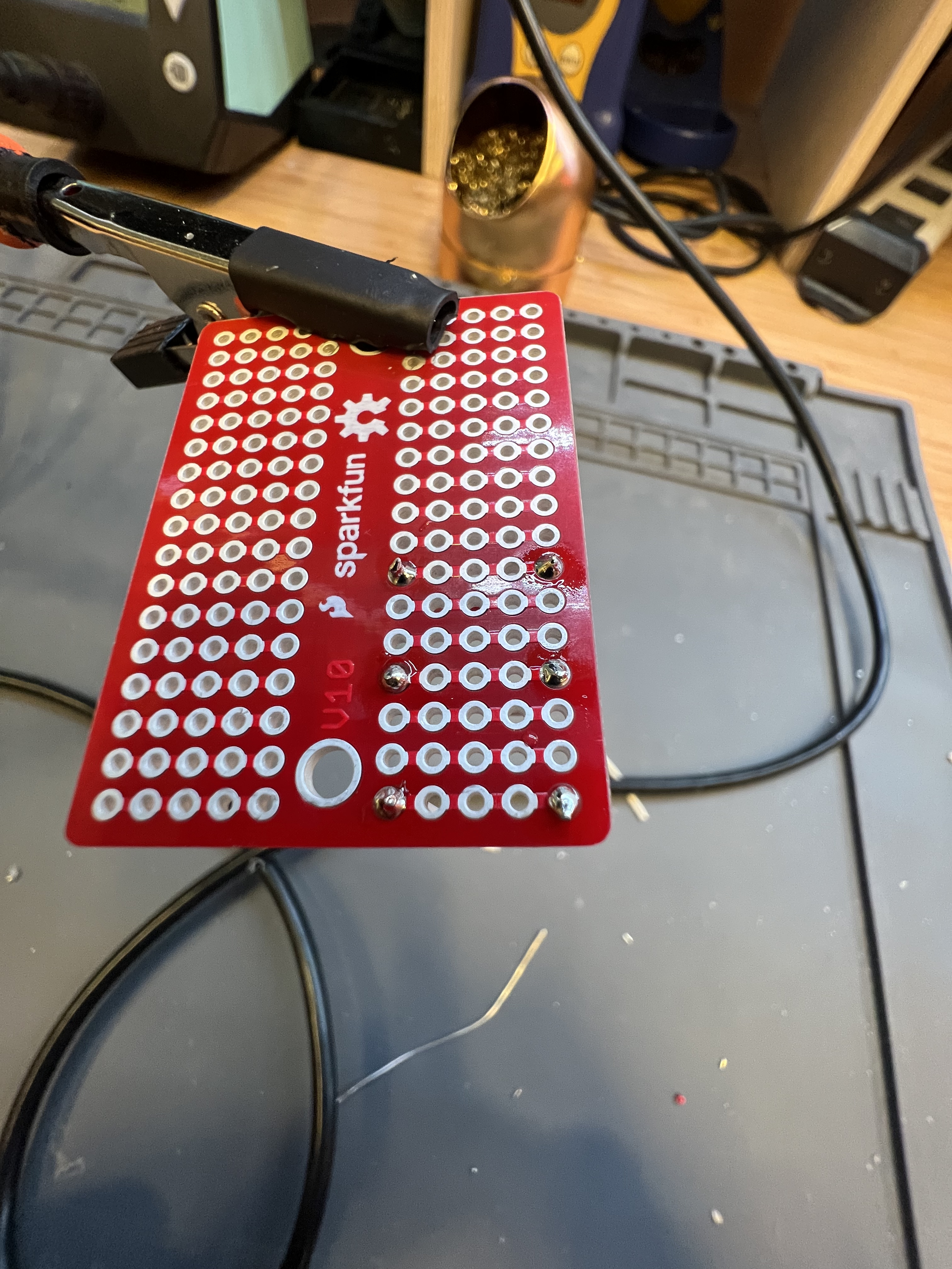
PART 2: SOLDERING WIRES TO PROTOBOARD
Procedure:
After turning the soldering iron on and getting it heated, we need to tin and clean the iron. Tinning is the process of melting and depositing solder over the tip of the soldering iron
After tinning, we need to clean the excess solder from the tip by rubbing the iron in the brass wire pad.
Once cleaned, the soldering iron is ready to be used.
Make sure you do the tinning + cleaning treatment every few minutes – soldering with the iron can quickly make it rough and unusable, which can be fixed by tinning and cleaning.
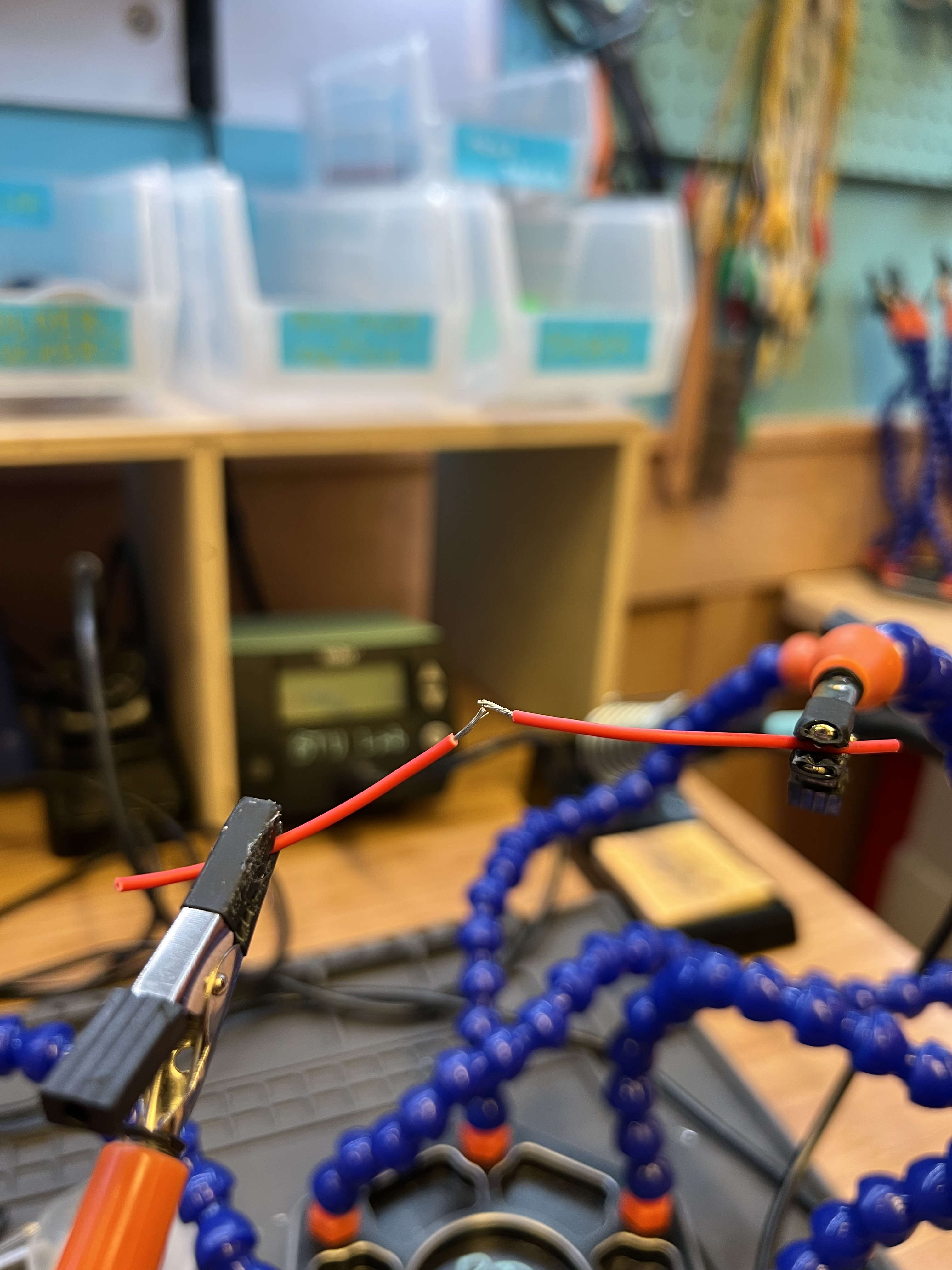
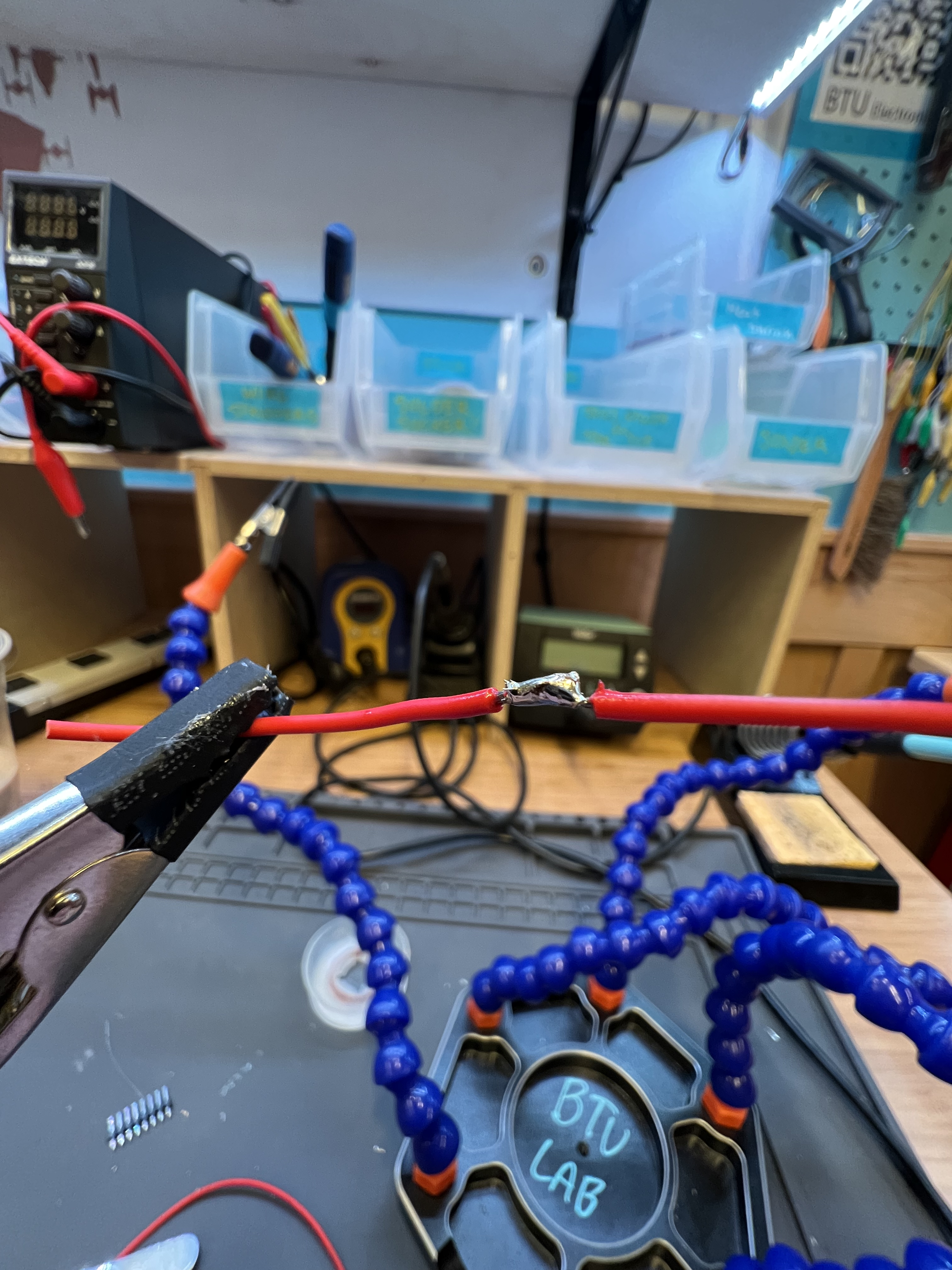
Take a small (4-inch) piece of stranded wire and strip off about 2 mm of one of the ends using a wire stripper
Roll up all the strands together (to make them adhere to each other), and insert the metallic part through one of the corner holes on the protoboard
Once inserted, apply some solder on the tip of the soldering iron, and bring it to the top of the exposed metallic part to solder the wire to that hole in the protoboard
As you see the liquid solder transfer to the metallic wire, slowly remove the soldering iron away to let the solder cool down and solidify
You should see a small blob of shiny solder on top of the wire that you put through the protoboard hole. You’ve just completed your first solder joint!
Be careful with how much solder you put on the joint. The liquid solder should just about cover the exposed wire and nothing more than that.
Now, you can go ahead and solder the other end of this wire to the protoboard as well! Pick a hole 3-4 holes away from the one you just soldered on, and follow the same procedure.
After attaching both sides of the stranded wire to the prototyping board, you can do the same with two small pieces of solid-core wire (3-4 holes away from the stranded wire joints)
Example of tinned soldering iron tip:
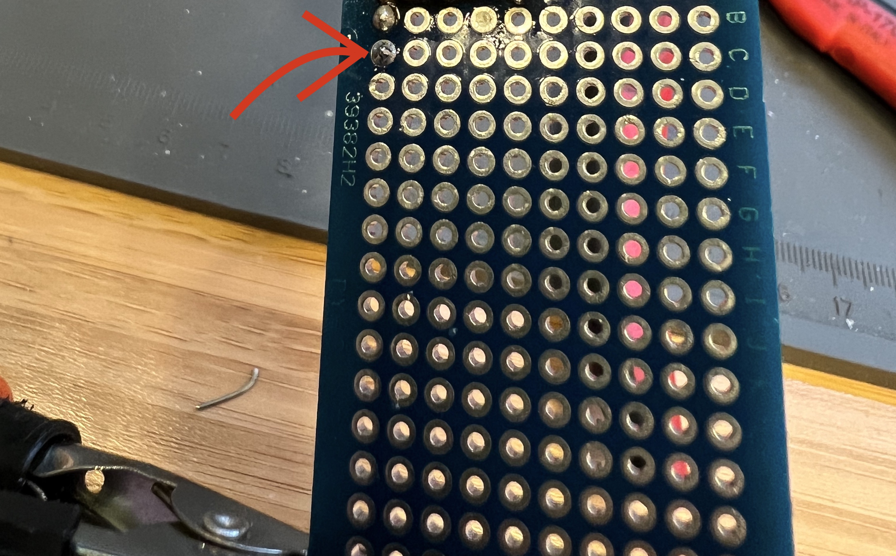
Example of wire solder joints:
Six solder joints:
Wires on the other side
Note: The red wire is stranded and the two white wires are solid core
Problems Faced and Conclusion:
There were no problems faced with this section of the lab everything went smoothly.I found it easier to solder the solid-core wire to the protoboard because it stayed put better.
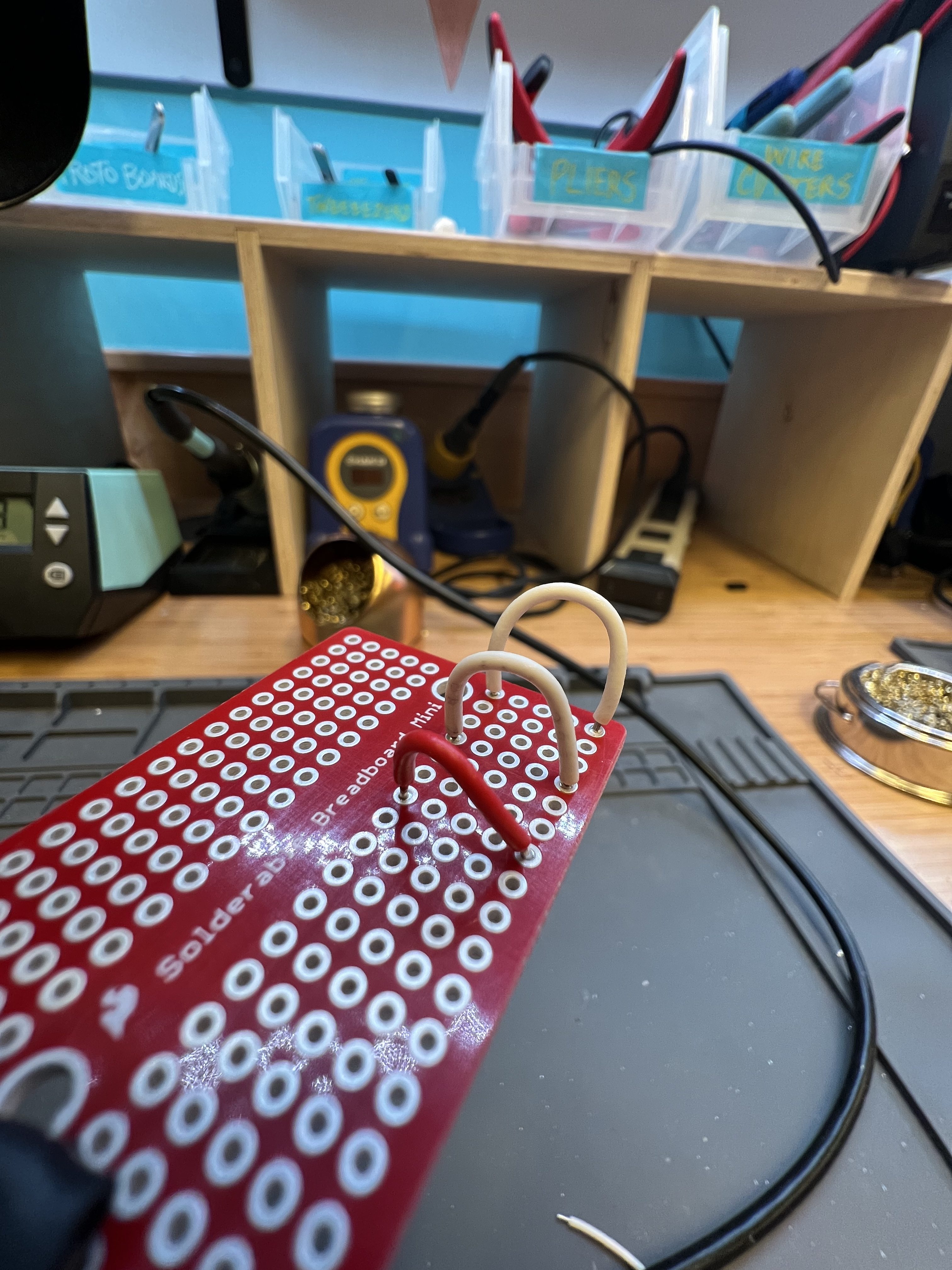
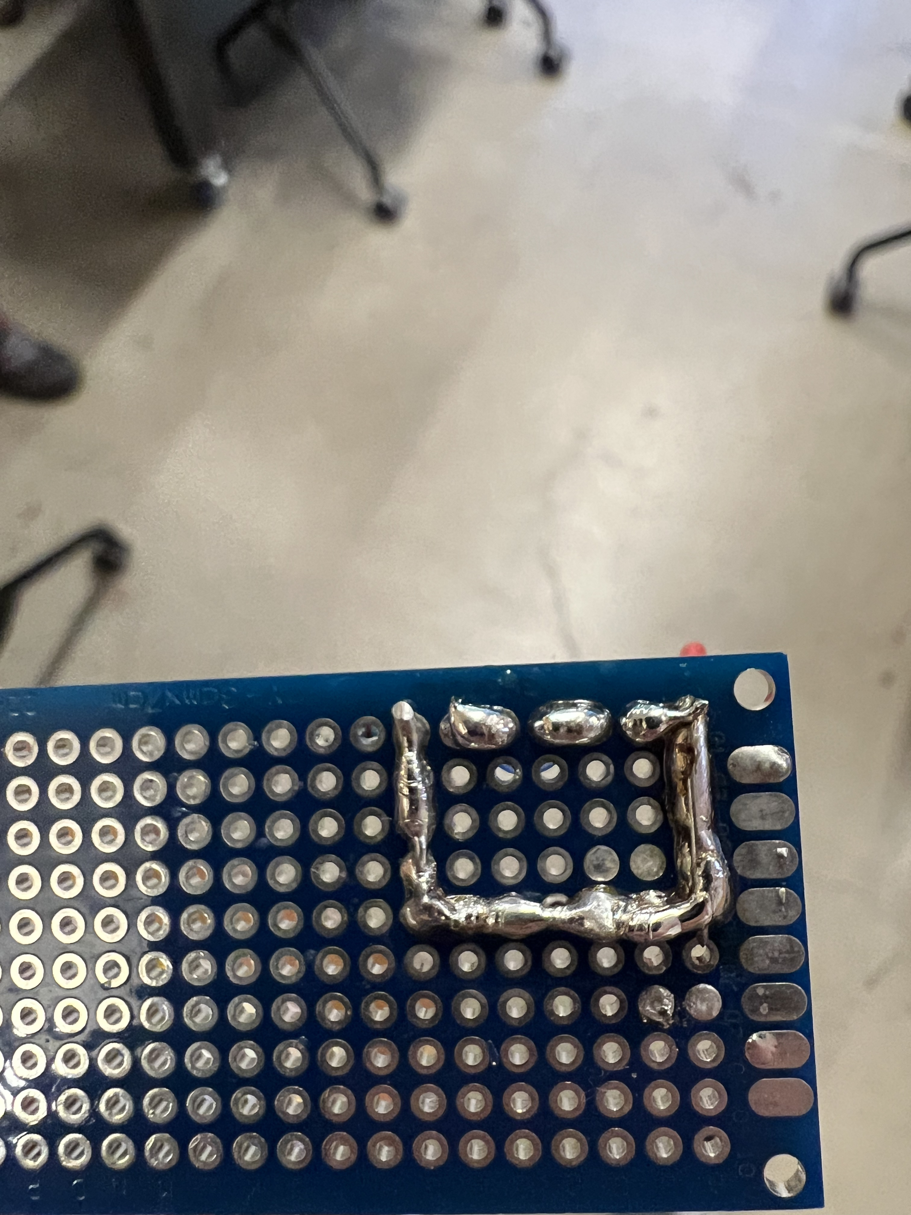
PART 3: BRIDGE OF SOLDER
Repeat same steps as previously stated
In order to create a bridge, we first need to apply solder on two adjacent holes in the protoboard, and after that, deposit more solder onto them while molding the solder to form a bridge between the two holes
Keep doing this for a series of adjacent holes, and you will end up with a trace between two separate points on the board.
3 Solder Bridges:
Note: These three solder bridges are wired in series for the Extra Volt circut later
Wires on the other side of the solder bridges:
Problems Faced and Conclusion:
This part of the lab was a bit more tedious and getting the solder to form bridges was definitely tricky.
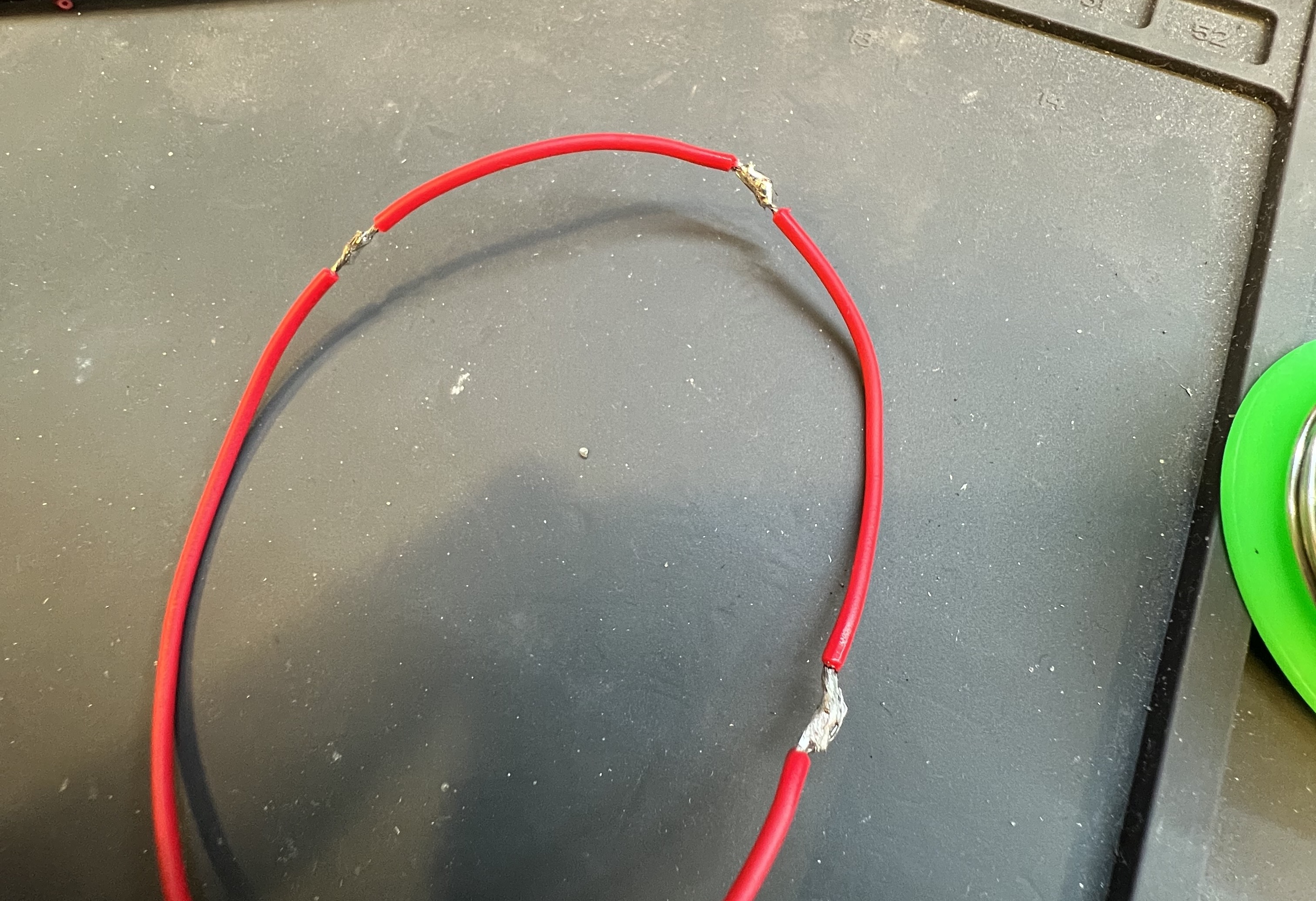
PART 4: SPLICING WIRES
Take 4 small (2-inch) pieces of stranded wires and strip their ends by about 2 mm using the wire stripper
Hold the individual pieces upright using helping hands, and apply solder to the exposed metal in the wires
Position the two wires such that the two exposed ends with solder are barely touching each other
Hold them steady while touching the point of contact with the soldering iron such that the solder melts on both wires and combines to form a bigger blob of solder
Once you see that the solder blob mostly covers the junction of the two wires, move the solder away and hold the wires steady until the solder completely solidifies
Wires pre splice:
Wires post splice:
Three splice joints:
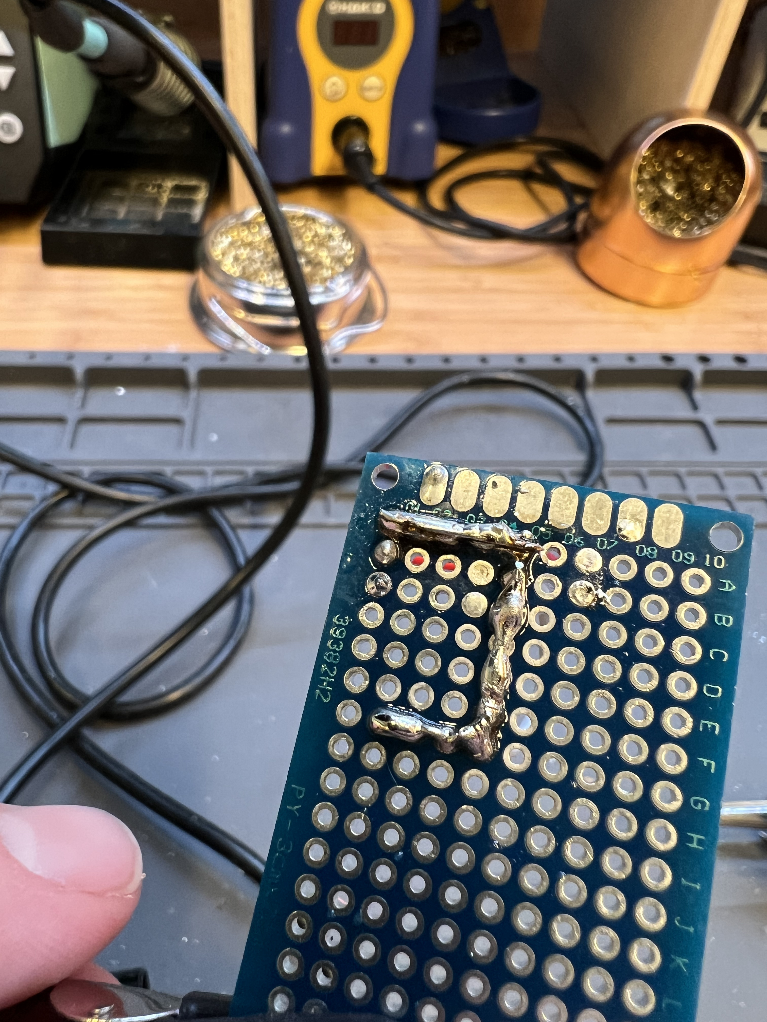
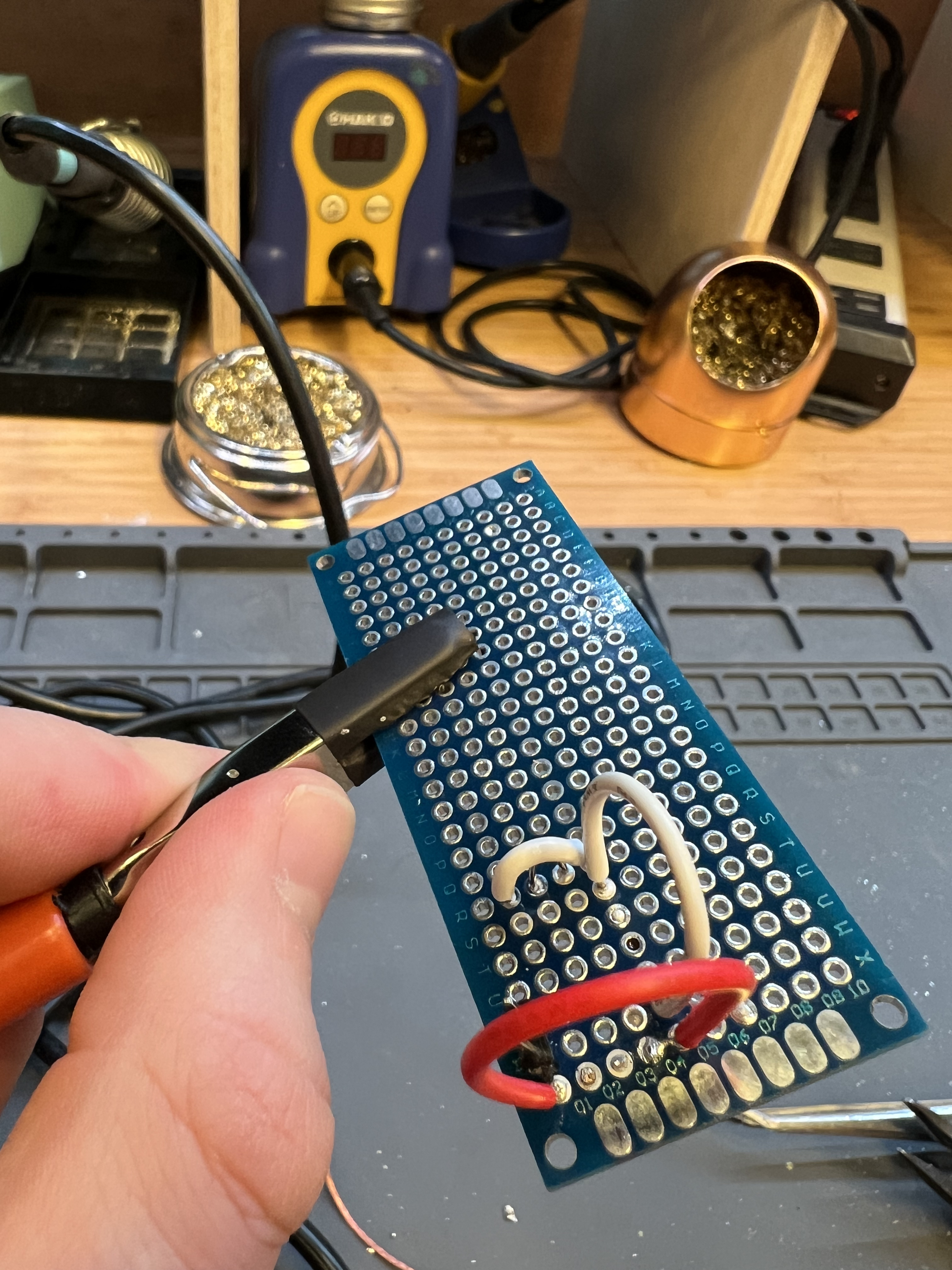
Extra Volt
Procedure:
Complete steps associated with creating solder bridges to create 3 solder bridges in series
Incorperate the pin header, LED, and 220 ohm resistor into the circut as shown in Lab 2
Plug in the the negative terminal of the pin header into the GND of the arduino controller and plug the positive terminal of the pin header into the pin 10 on the arduino.
Install the Arduino Integrated Development Environment (IDE)
Navigate to File > Examples > 01. Basics > Blink and click to open the Blink example in a new window
Declare a global variable equal to 10 outside of the setup() function and the loop() functional declarations: “int LED_PIN = 10;”
Replace LED_BUILTIN everywhere with our variables name:“int LED_PIN = 10;”
Upload this code to the board by clicking on the arrow button on the toolbar
Wait for the "Done Uploading" message
Watch the LED on the Arduino Board blink repeatedly
Successful LED soldered circuit
Back of Extra Volt Protoboard
Problems Faced and Conclusion:
I had to use the potentiometer a bit for this Extra Volt since initially the solder connections initially weren't transferring current so I had to clean them up a bit and add more solder.
Lab 4
Description:
In this lab, we begin interacting with electrical circuits in a more advanced
fashion—using analog input! We will learn how to use our Arduino to take analog
measurements from components like a potentiometer and an analog joystick, which is
like a multi-dimensional potentiometer. We will use these inputs to control different
LED arrangements and create a simple Whack-a-mole game that is then made more advanced
in the Extra Volt!
Materials Used:
Arduino (Elegoo) Uno R3 Controller Board
USB Cable
USB Adapter
Breadboard Jumper Wire
Resistors
LEDs
Multimeter
Potentiometer 10k
Joystick Module
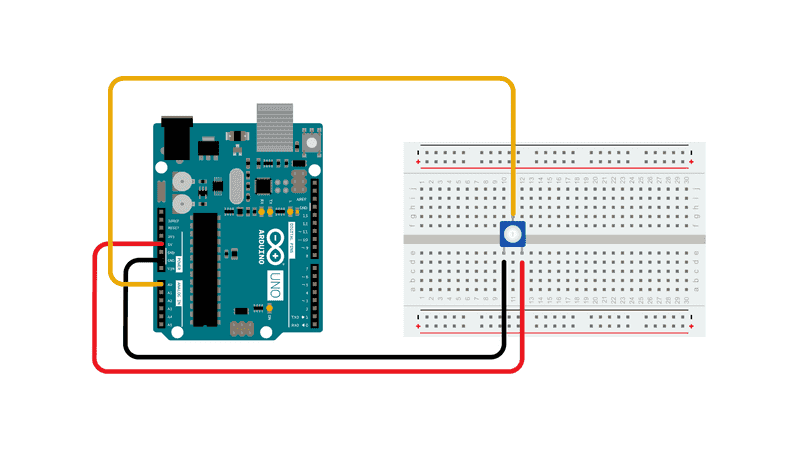
PART 1: USING A POTENTIOMETER
Procedure:
Our kit includes a rotary potentiometer with three pins, two of which are “fixed ends”, and the third is a “variable end”, which, when we rotate the knob of the potentiometer, changes the resistance on the two sides of the variable end.
Connect the two fixed sides to power (5V) (pin 1) and ground (pin 3)
Measure the voltage on the variable end by connecting it to Analog pin A0
When the potentiometer is dialed in all the way to the left, the voltage between pin 1 and pin 2 would be 0 Ω, and the voltage at pin 2 would be 5V. As we rotate the knob, the resistance between pin 1 and pin 2 would increase up to 10kΩ
Follow code directions listed below
Potentiometer Circut Schematic
Potentiometer Circut:
Code for Part 1:
Video of potentiometer working
Problems Faced and Conclusion:
I didn't have many problems for this section of the lab I just had to mess around with the code a bit.
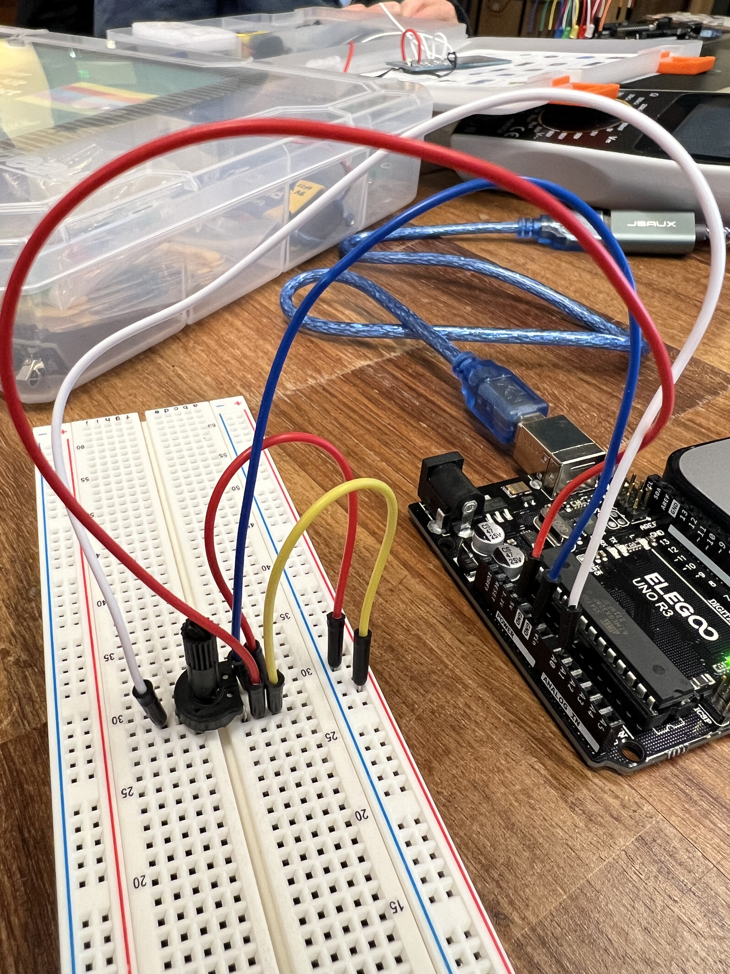
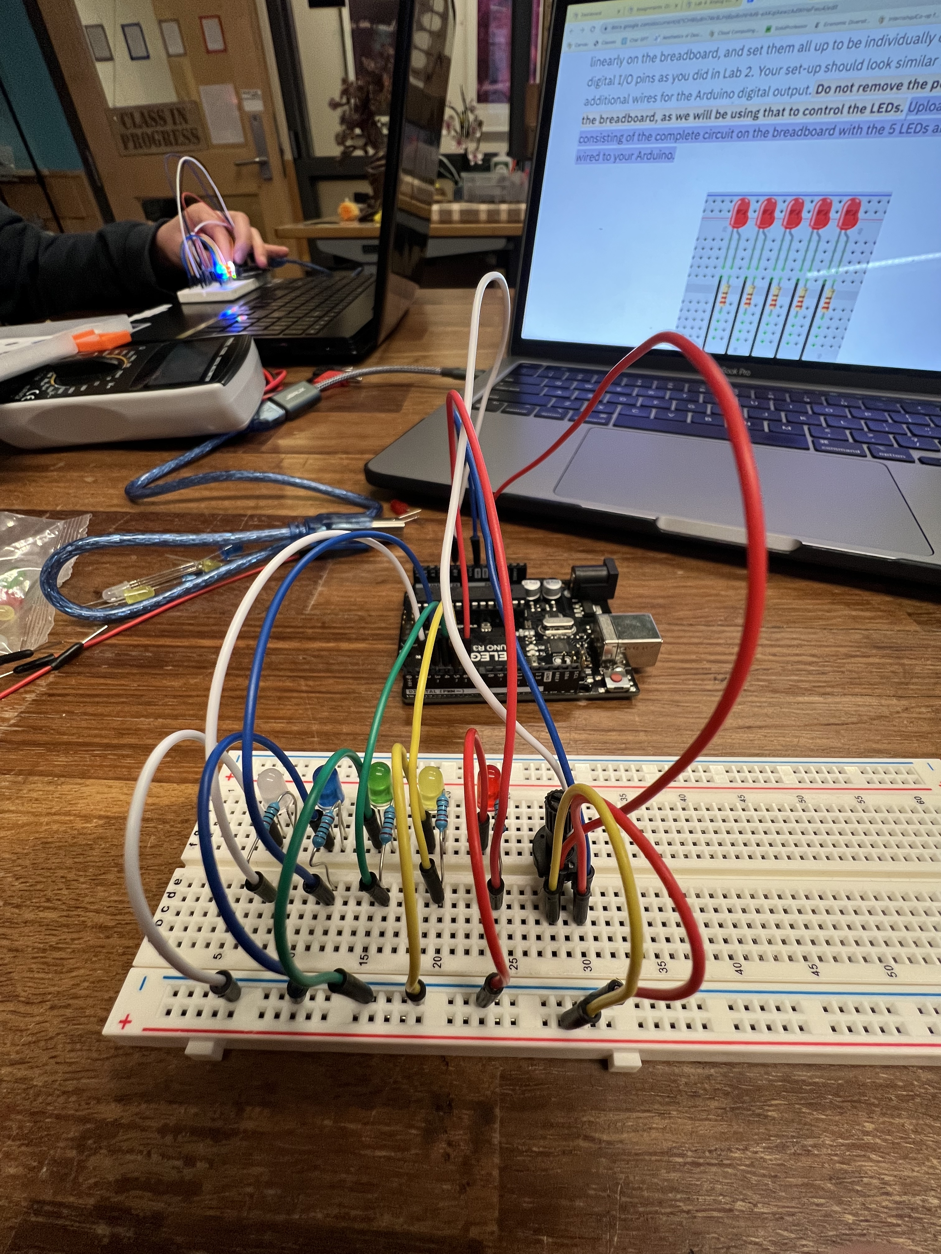
Part 2: LIGHT ‘EM UP WITH A POTENTIOMETER
Procedure:
To begin, take 5 LEDs from your kit (with colors of your choice), arrange them linearly on the breadboard, and set them all up to be individually digitally controlled using the digital I/O pins as you did in Lab 2.
Do not remove the potentiometer circuit from the breadboard, as we will be using that to control the LEDs
Follow the code as listed below to create a sketch where no LEDs are turned on if the potentiometer is turned all the way to the left (when the value reads 0). As you slightly rotate the knob, one LED turns on. If you rotate it a little more, two LEDs turn on, and so on, until all the 5 LEDs are turned on when the potentiometer is dialed all the way to the other side
Linear arrangement of 5 LEDs:
Video of LEDs lighting up in sequence:
Code for Part 2:
Problems Faced and Conclusion:
I didn't have many problems for this section of the lab I just had to mess around with the code a bit.
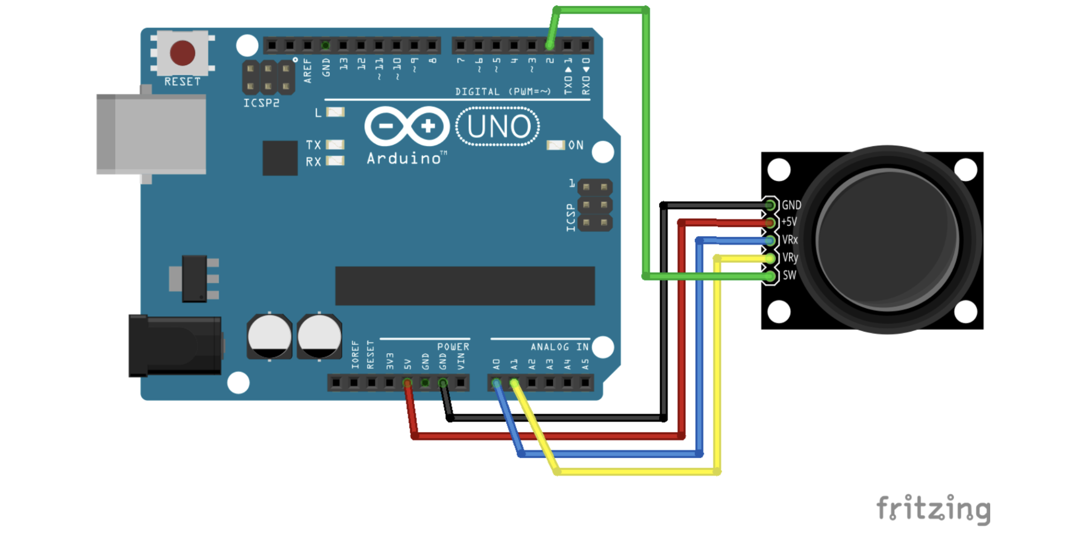
PART 3: JOYSTICK FOR ARDUINO
Procedure:
After learning about how to use a potentiometer, we can move on to working with an analog joystick!
This joystick is simply two potentiometers and a push button combined into one neat package.
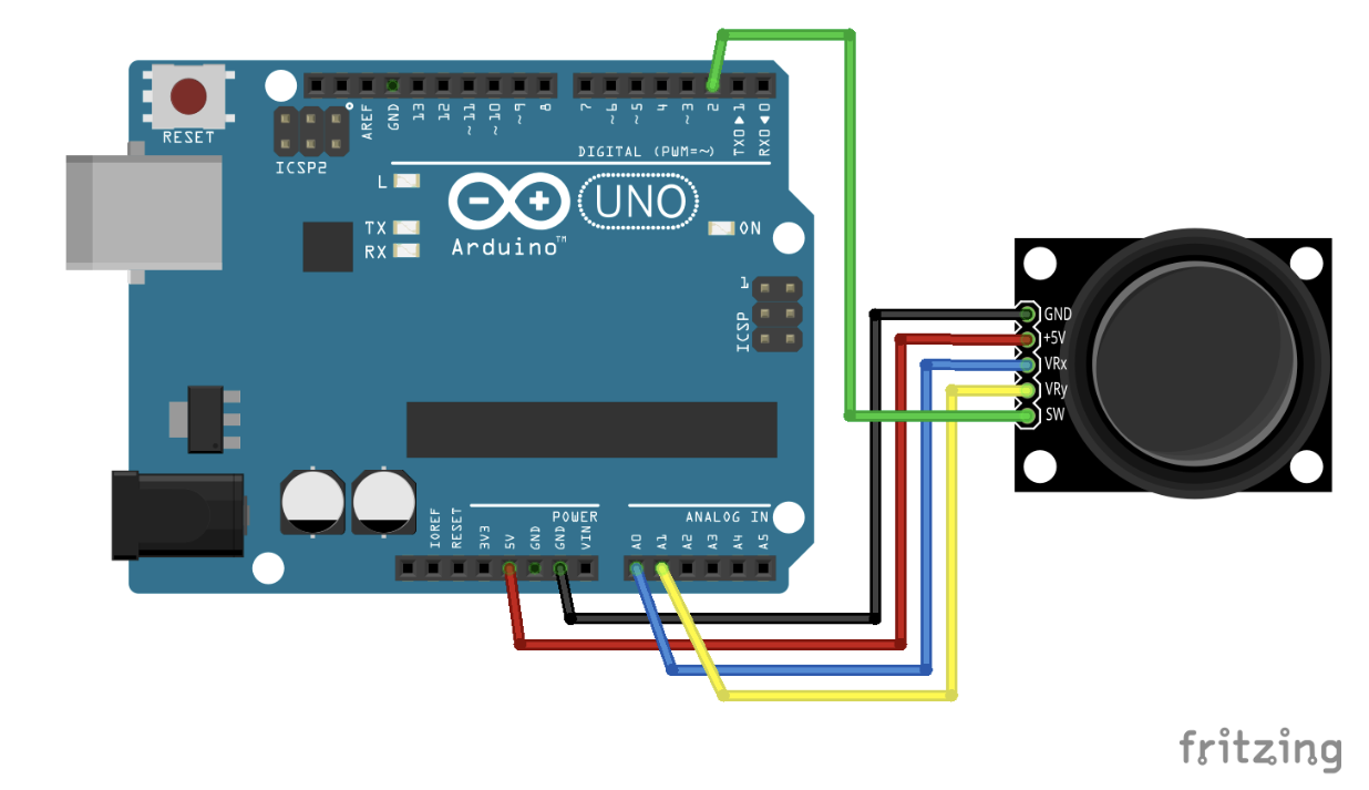
You will notice that the module has 5 pins: GND, +5V, VRx, VRy, SW. The first two are the ground and power pins, while the third and the fourth are variable pins of the two potentiometers – one for movement along the x-direction (VRx) and the other for movement along the y-direction (VRy).
This means that these two pins need to be connected to any of the analog pins on the Arduino (A0-A5)
The last pin SW is for the push button, which goes HIGH when you press on the joystick, and LOW otherwise – it can be connected to a digital pin.
You can remove the potentiometer breadboard but retain the 5 LEDs, as we will be using them in the next part.
Joystick Schematic:
Joystick Circut:
Code for Part 3:
Average Values:
The average values of both x and y directions when the joystick is centered (home position) are X: 514 Y: 514
The values when the joystick is moved all the way to the left are X: 0 Y: 513
The values when the joystick is moved all the way to the right are X: 1023 Y: 513
The values when the joystick is moved all the way down are X: 1023 X: 513 Y: 1023
Up: X:0 Y: 513
Top right corner: X: 1023 Y: 120
Top left corner: X: 0 Y: 0
Bottom right corner: X: 1023 Y: 1023
Bottom left corner: X: 0 Y: 1023
Video of Joystick working:
Problems Faced and Conclusion:
This part of the lab didn't give me too much trouble just getting all the X and Y values down was a bit of a pain.
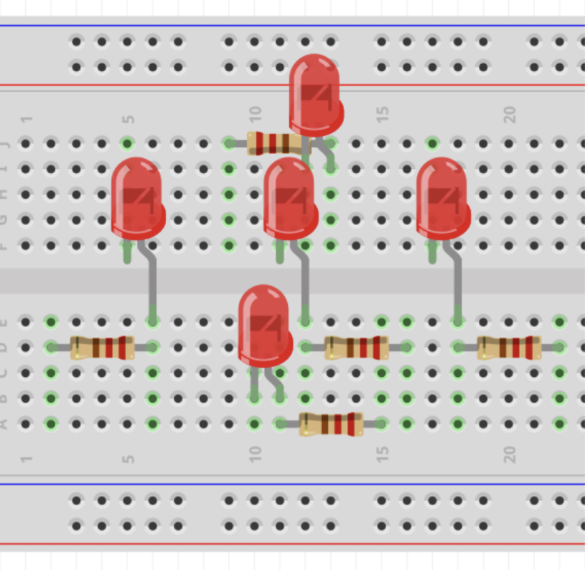
PART 4: LIGHT ‘EM UP WITH A JOYSTICK
Rearrange the 5 LEDs on the breadboard into a ‘plus (+)’ layout as shown below.
Be careful of where the LEDs are connected on the breadboard – the pins of two different LEDs should not be in the same row of the breadboard, else we will not be able to control them independently!
After setting up the circuit, we want to program the Arduino to control which LEDs get turned on based on the input from the joystick. The sketch should perform the following behavior:
When the joystick is moved up, the top LED turns on. Similarly, joystick to down → bottom LED on, joystick to left → left LED on, and joystick to right → right LED on.
When the joystick is moved diagonally to top-right, both the top and the right LED turn on. Similarly, joystick to top-left → top and left LED on, joystick to bottom-right → bottom and right LED on, and joystick to bottom-left → bottom and left LED on.
When the joystick is centered, only the center LED should be on.
Follow the code listed below
Plus LED Circuit Schematic:
Video of Joystick lighting up LEDs
Code for JOYSTICK controlled LEDs
Problems Faced and Conclusion:
The only problems I had with this section of the lab was getting the circuit right since that was a bit tricky.
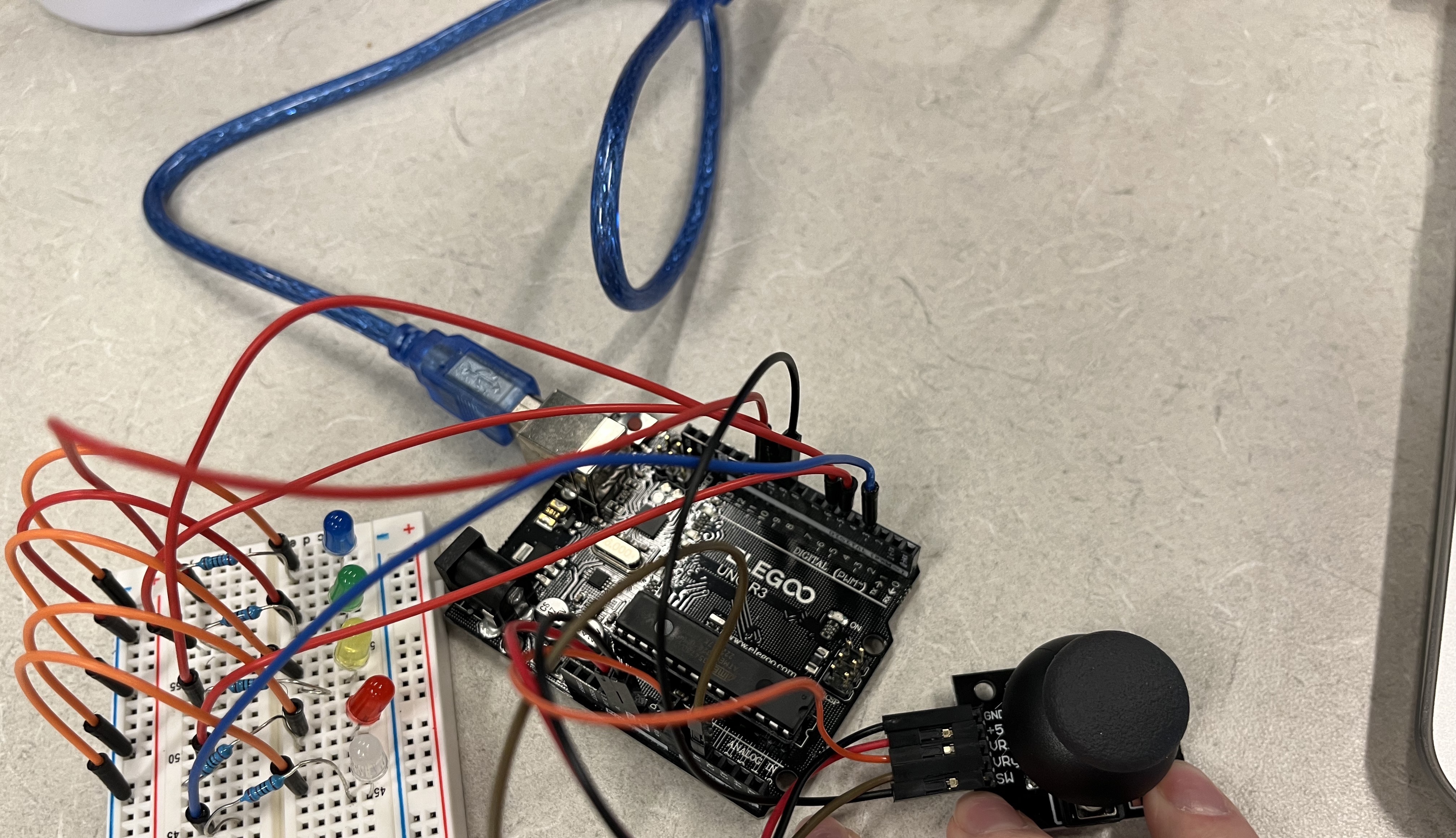
PART 5: BASIC LED WHACK-A-MOLE
Procedure:
In this part of the lab, we will use the joystick and the plus-arrangement of the LEDs to create a simple whack-a-mole game! The gameplay of this game should be as follows:
Each round begins with a welcome/ready message on the serial monitor and two 500ms long blinks of the center LED. After the blinks, all LEDs are off, and the game waits for 1 second for the player to get ready. When the 1 second elapses, a timer starts running (Hint: use a start-time variable to track the time).
The game randomly chooses one of the four corner LEDs (top, bottom, left, right) to turn on (Hint: use the random() function from Lab 2). The LED stays on until the player moves the joystick in its direction (e.g. moving the joystick up when the top LED is on/active).
As soon as the joystick is moved in the direction of the active LED, it turns off, and the game randomly chooses another LED to turn on. The new LED can be the same as the previous LED. This occurs 20 times.
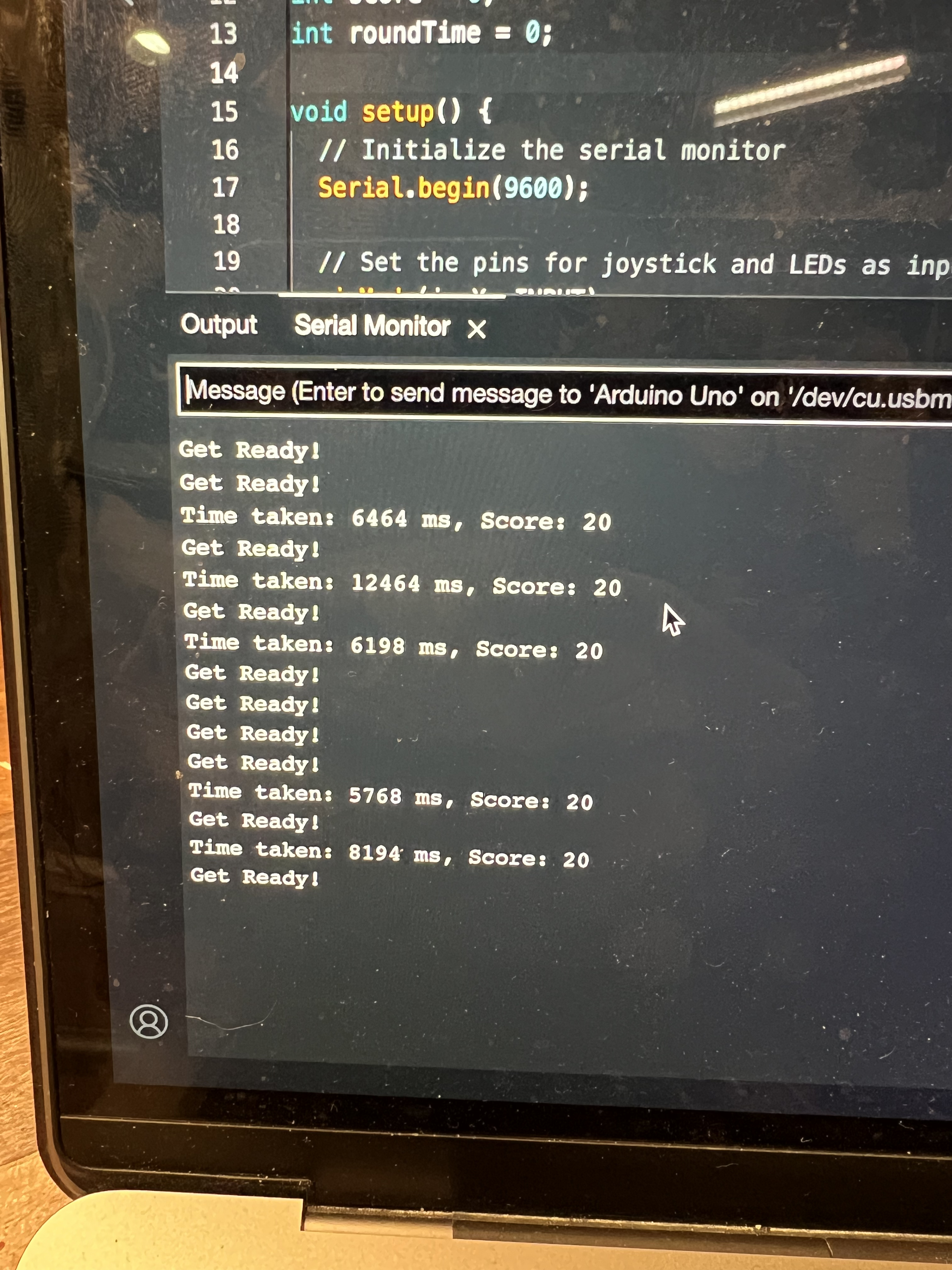
After 20 LEDs have been activated and consequently “whacked” using the joystick, the round is over. The timer is stopped and the total time taken by the player is displayed on the serial monitor.
At the end of the round, the game waits for 3 seconds before going back to step (1) and restarting the round.
Code for Basic LED WHACK-A-MOLE game
Video of BASIC LED WHACK-A-MOLE GAME
Serial Monitor Output:
Problems Faced and Conclusion:
Getting the code to work for this was a bit tedious but it turned out well.
Lab 5
Description:
This lab is about having the Arduino interact with the world using analog outputs! While we have been using LEDs to output from the Arduino in the past few labs (remember LED Reaction Game and Whack-A-MoLED?), we will now create some complex output from the Arduino in two contexts – visual and sound. In the first two parts of the lab, we will light up the RGB LED in different colors. In the latter two parts, we will create interesting sounds using a piezo buzzer. Finally, in the Extra Volt, you will get the chance to combine the two outputs to create your own audio-visualizer!
Materials Used:
Arduino (Elegoo) Uno R3 Controller Board
USB Cable
USB Adapter
Breadboard Jumper Wire
Resistors
LEDs
Joystick Module
Passive Buzzer
Multimeter
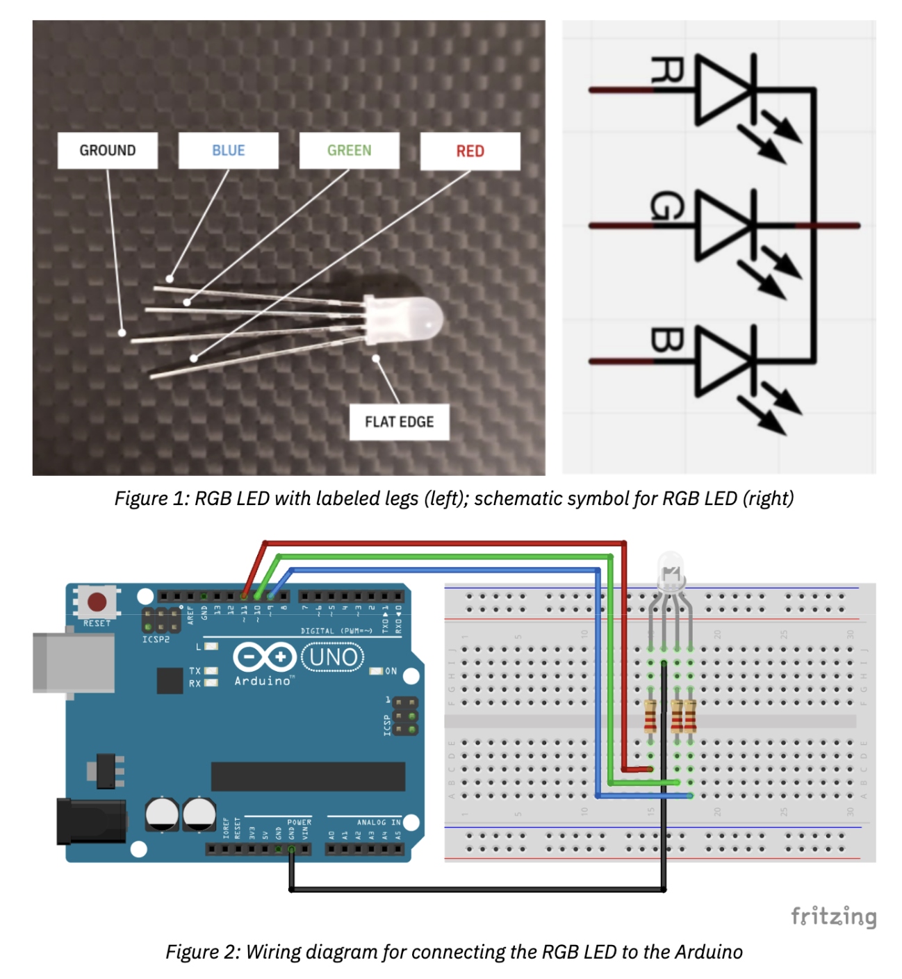
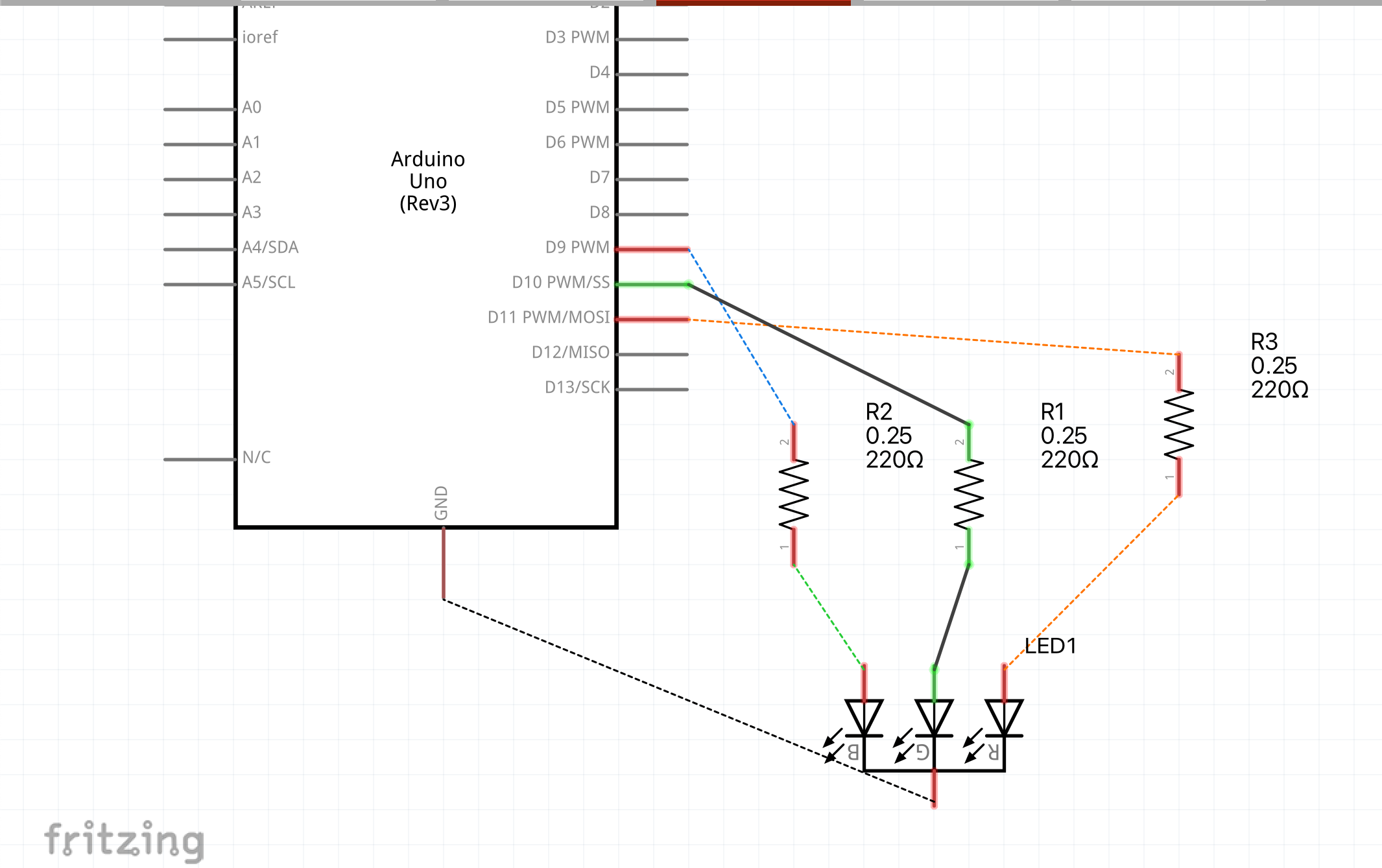
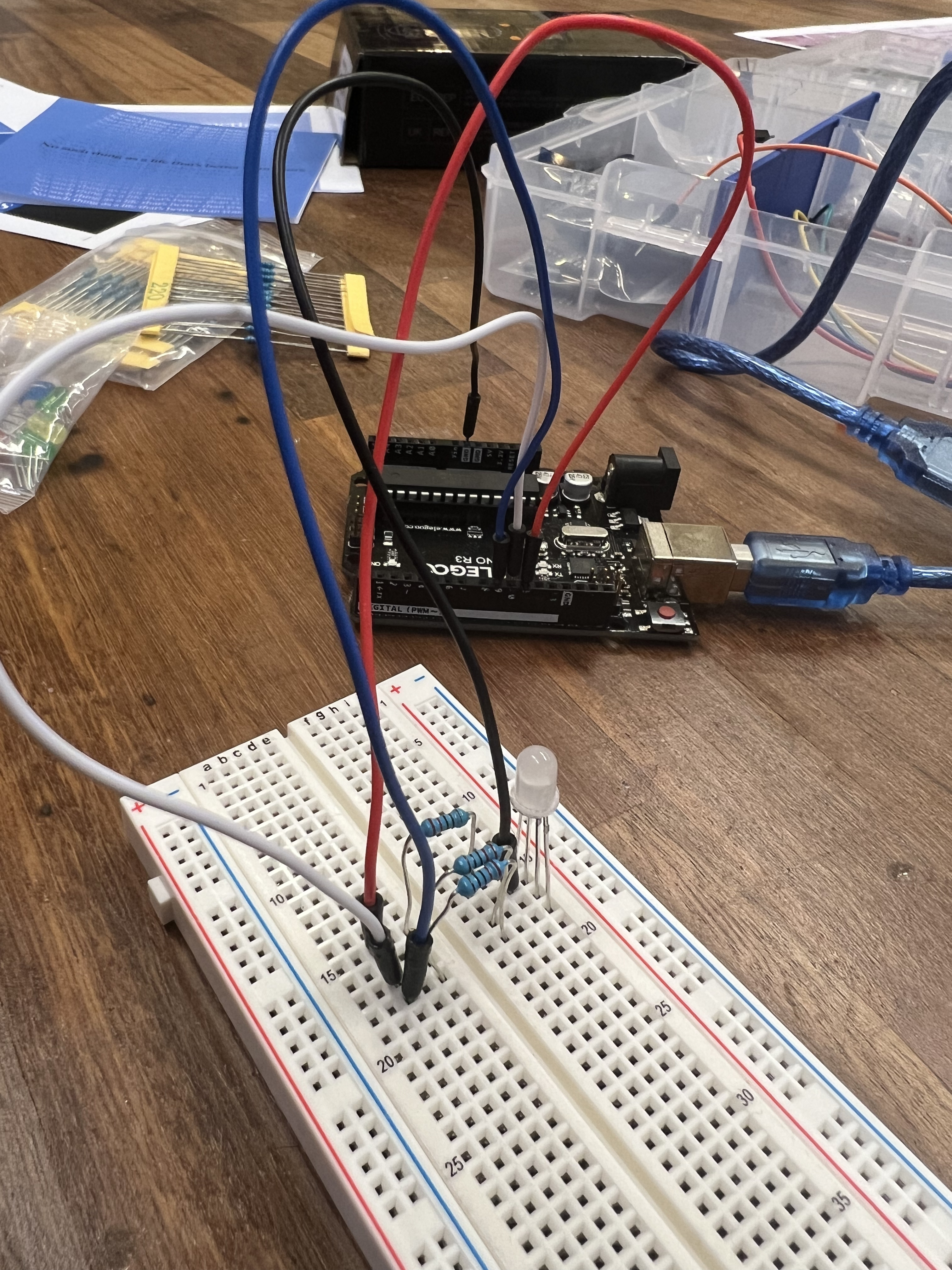
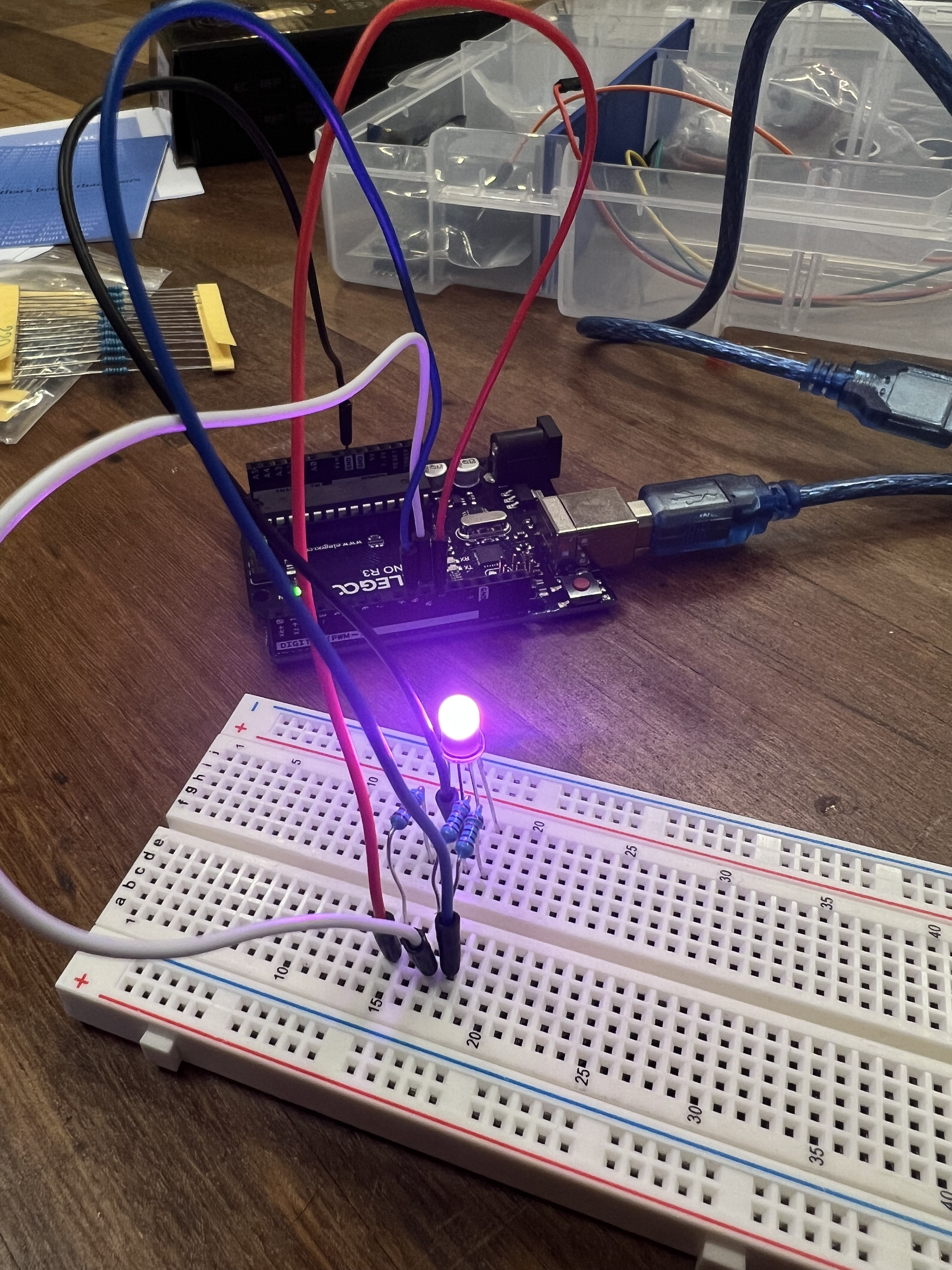
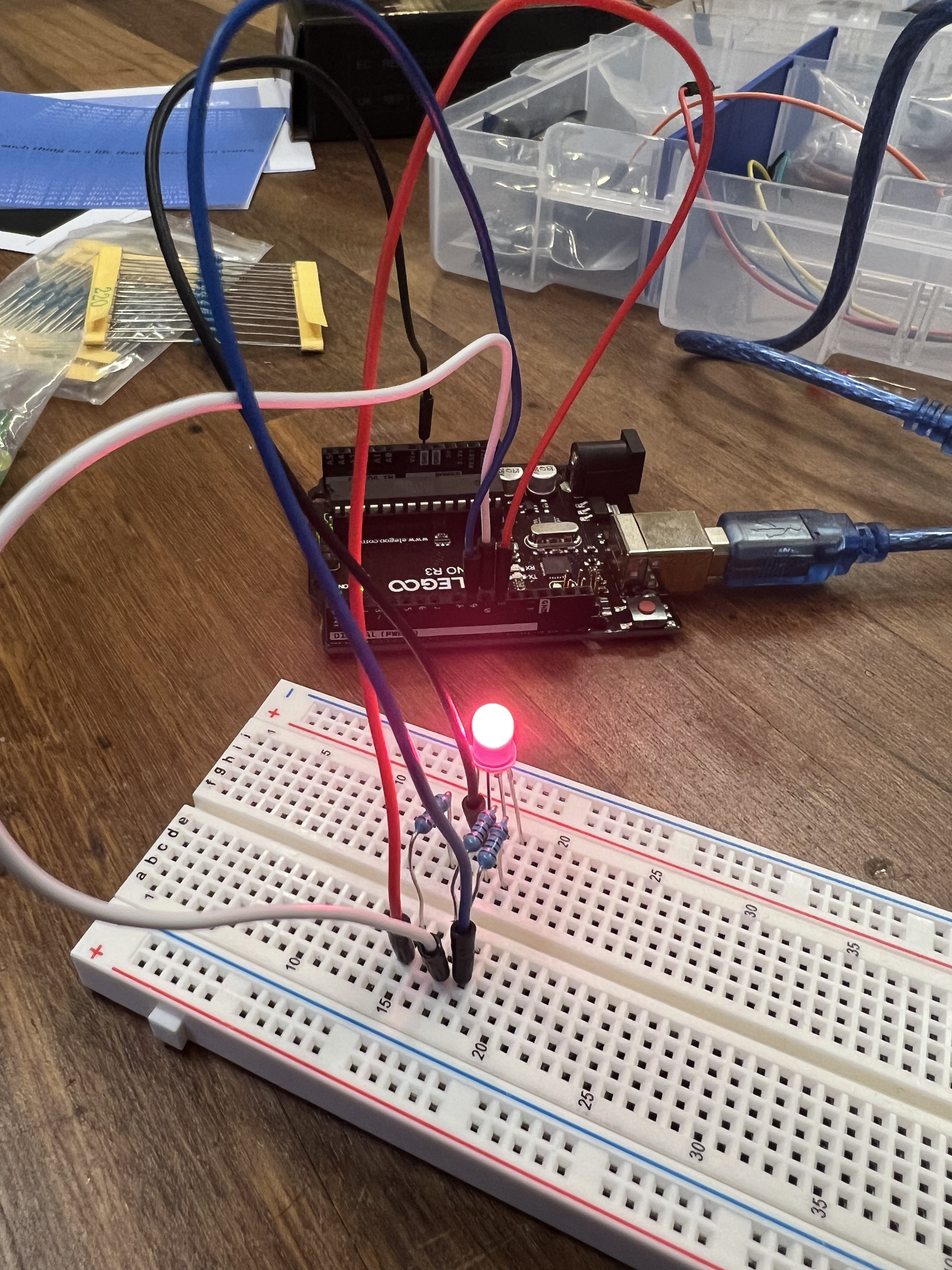
PART 1: WIRING UP THE RGB LED
Procedure:
In the first part of the lab, we will connect the RGB LED from our kits to the Arduino
In the RGB LED included in our kit, the longest leg is for ground, which is also the second pin from the flat side of the LED bulb
Be super careful while connecting the four pins to the Arduino and double check before powering the circuit
An important thing to note is that not all the digital pins on the Arduino support Pulse-Width Modulation, which is what we need to make the RGB LED turn on into different colors
Only pins with numbers labeled with a ‘~’ next to them allow PWM – which include 3, 5, 6, 9, 10, 11 on the Arduino Uno board
Follow the code as listed below. You can change the R,G, and B values in the analogWrite() functions to create different colors
LED Pins + Wiring Diagram:
Fritzing Schematic:
Part 1 Code:
RGB LED Circuit:
Purple LED:
Red LED:
Blue LED:
Yellow LED:
Problems Faced and Conclusion:
I didn't face any problems for this section
PART 2: DYNAMIC COLOR CHANGER WITH JOYSTICK
Procedure:
In this part, we will use the analog joystick from our kits to change the colors produced on the RGB LED
Connect the joystick to the Arduino as we did in the previous lab (feel free to refer to Lab 4 handout)
Write an Arduino sketch that detects the x and y values of the joystick and maps them to two colors (out of R, G, B) of your choice in the RGB colors space
For example, you could have the x-value determine the R brightness, while the y-value determine the B brightness. For the third color (in this case, G), use a random value.
Follow the code listed below
Which resistor should be used?
A 220 ohm resistor needs to be used for the RGB light
Video of Joystick LED control working
Part 2 Code
Problems Faced and Conclusion:
At first the LED was a bit laggy but I was able to fix it by removing the delay
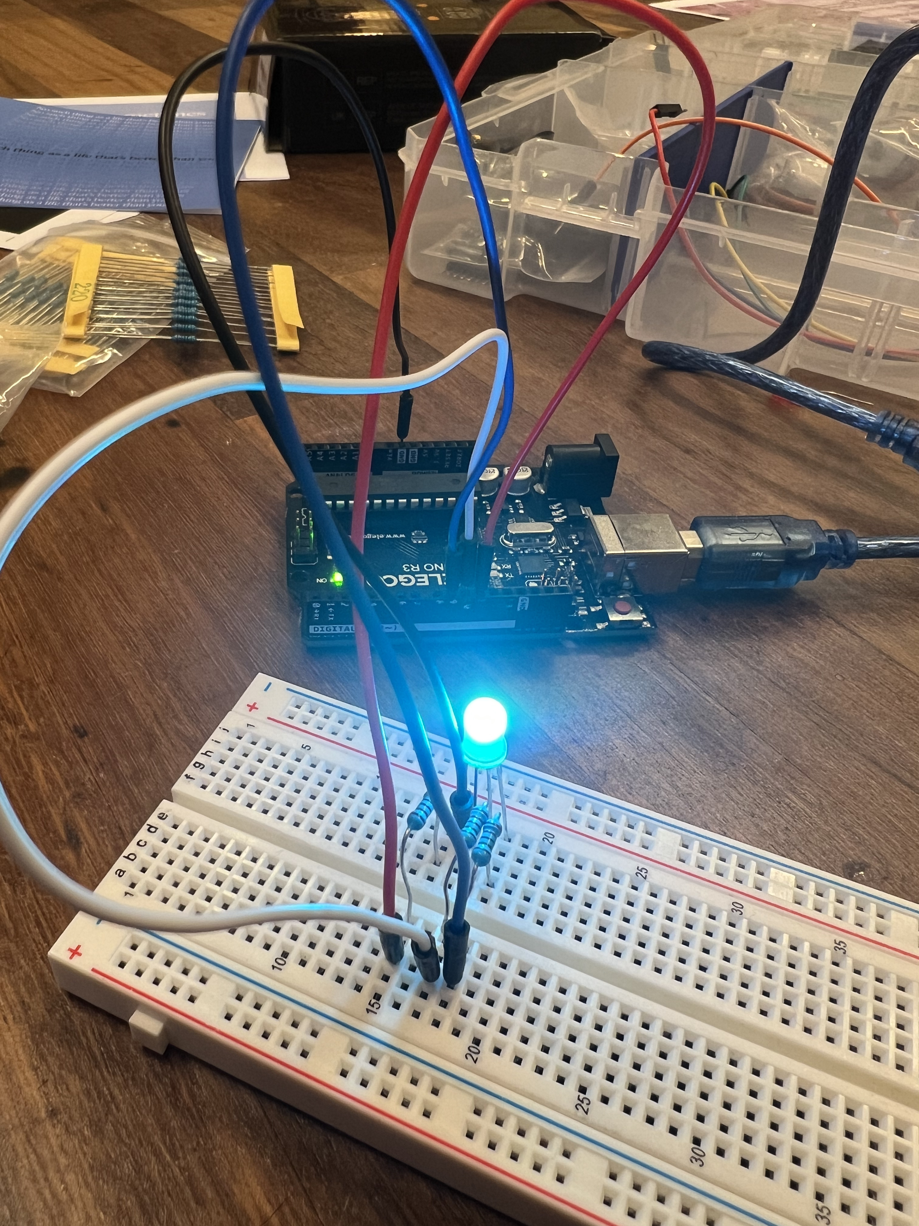
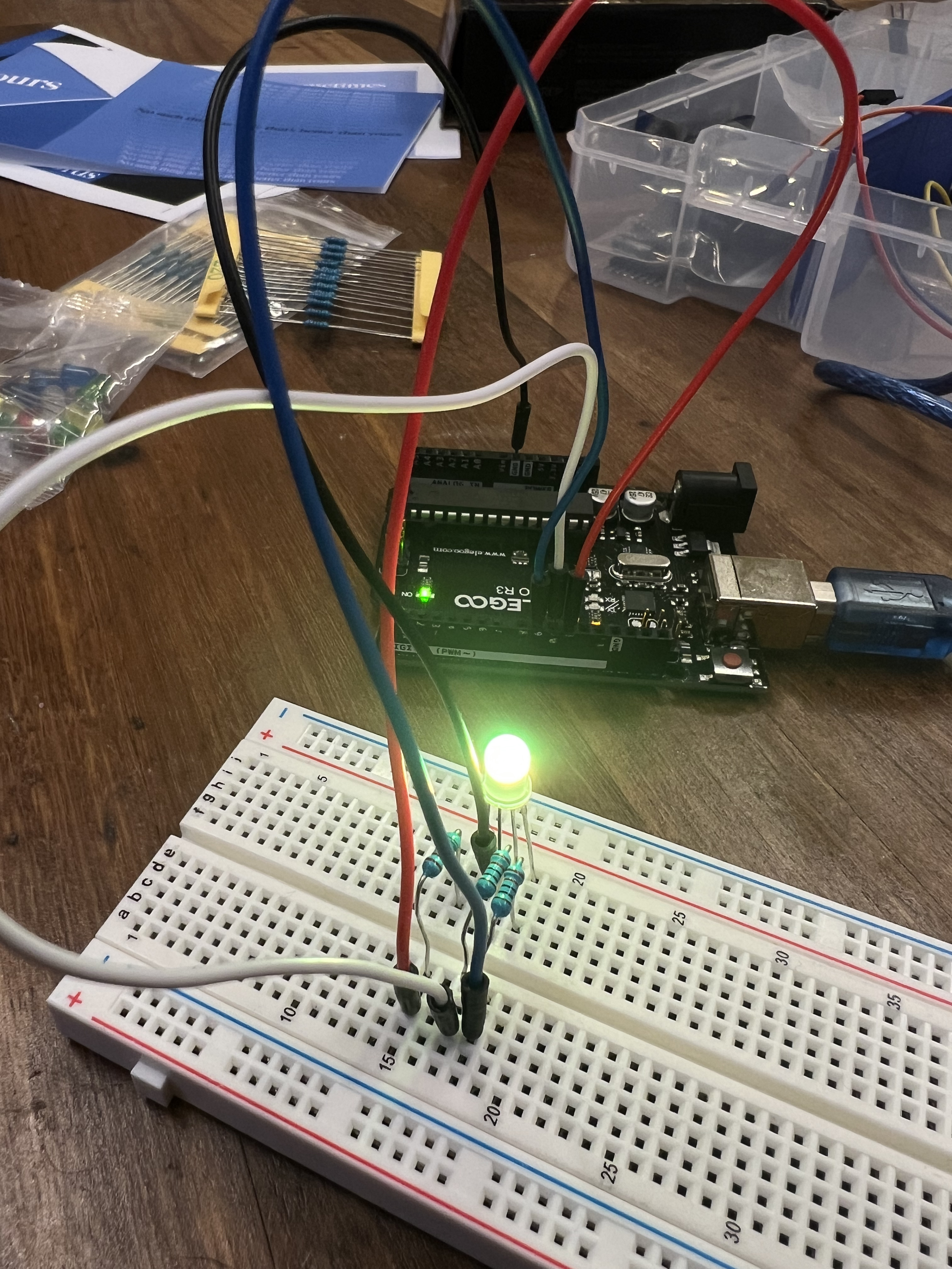
PART 3: MUSICAL NOTES WITH PASSIVE BUZZER
In this lab, we will be using the passive buzzer to generate different sounds. Both the buzzers in the kit look very similar, so take care to pick the one with the exposed green PCB on the underside, and no white sticker on the top.
Note that the buzzers have polarity—their positive pin can only be connected to a positive terminal; and their negative pin can only be connected to a negative terminal. If you plug them in reverse, you will irreversibly damage the component.
Connect the passive buzzer to the Arduino such that the positive terminal (with the + icon) is wired to a digital pin and the negative terminal is connected to the ground
The buzzer can be connected to any of the digital pins on the Arduino – not only the PWM ones labeled as ‘~’
Follow the code listed below
Buzzer circuit:
Fritzing schematic
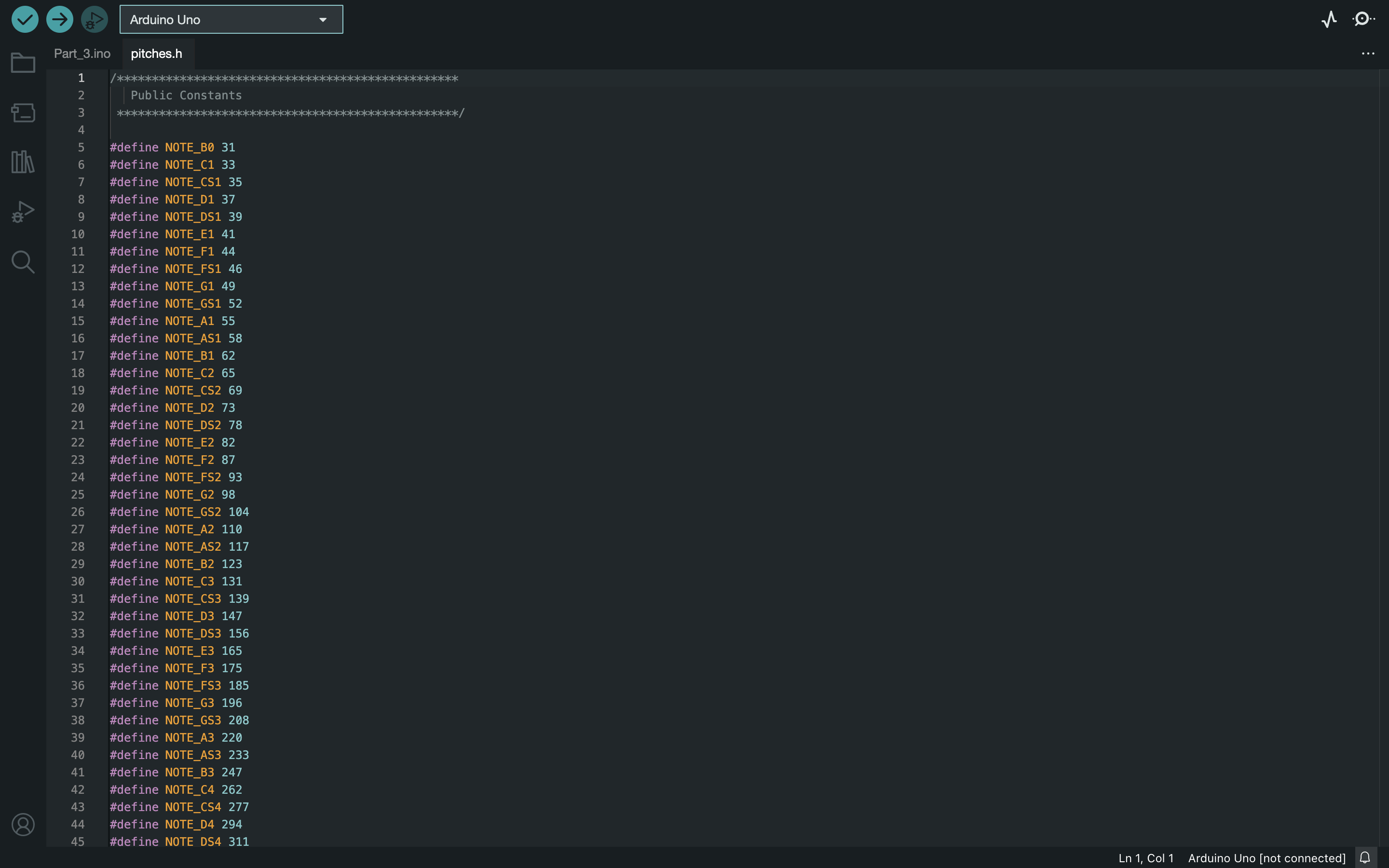
Screnshot of pitches.h file open
Video of 440hz beep
Code for 440hz beep
Video of modified note
Code for modified note
Problems Faced and Conclusion:
I forgot to ground the circuit initially so I had to figute that out.
PART 4: MELODY FROM THE BUZZER
Procedure:
Use the same circuit from Part 3
Follow the code listed below to create the songs
Video of given melody on buzzer
Code for given melody
Video of personal song
Code for personal song
Problems Faced and Conclusion:
It was a bit challenging to get the code to work but other than that this part went smoothly.
Lab 6
Description:
In this lab, we will be working with motors! Most of you have probably experienced motors in some form, whether it is the motor in your table fan, or in your RC car or drone. Motors come in different flavors, and we will be working with two types of motors in your kit for this lab – the servo motor and the DC motor. We will be connecting these to our Arduino boards in different ways and controlling them using the potentiometer and the joystick, and finally make an oscillating toy fan.
Materials Used:
Arduino (Elegoo) Uno R3 Controller Board
USB Cable
USB Adapter
Breadboard Jumper Wire
Resistors
Power Supply Module
Servo Motor SG90
DC Motor and Fan Blade
L293D IC
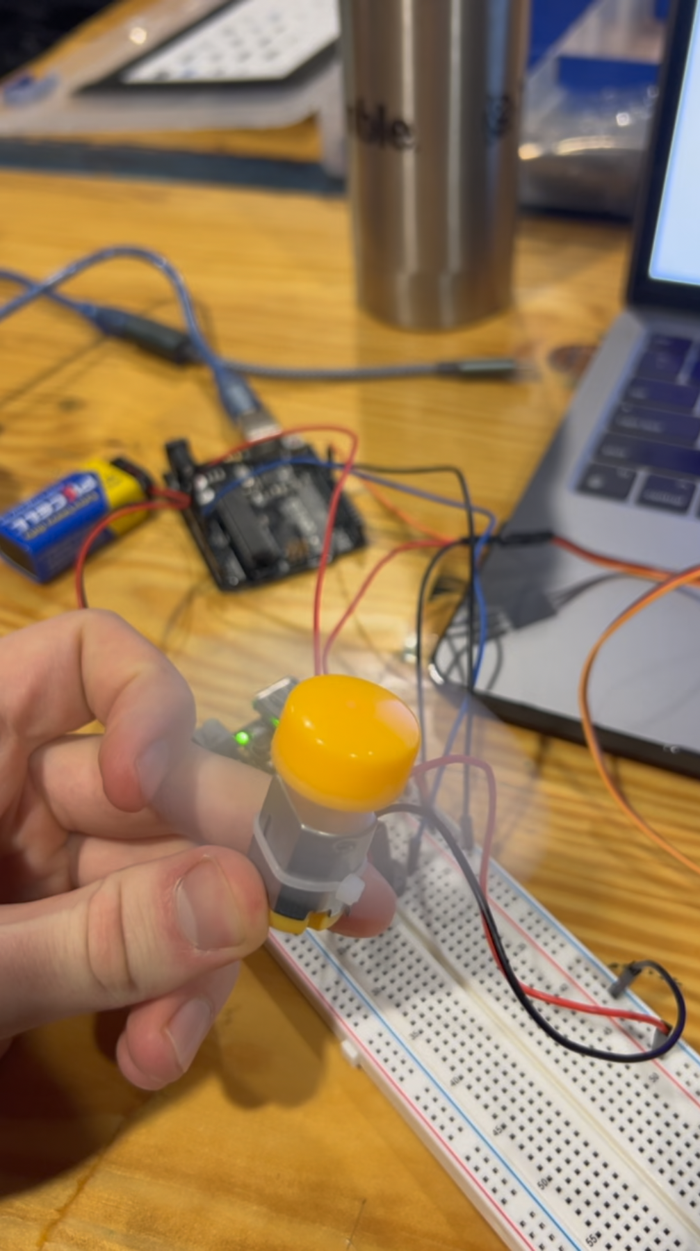
Button
Potentiometer
9V Battery with Snap-on Connector
Multimeter
PART 0: SETTING UP POWER
Procedure:
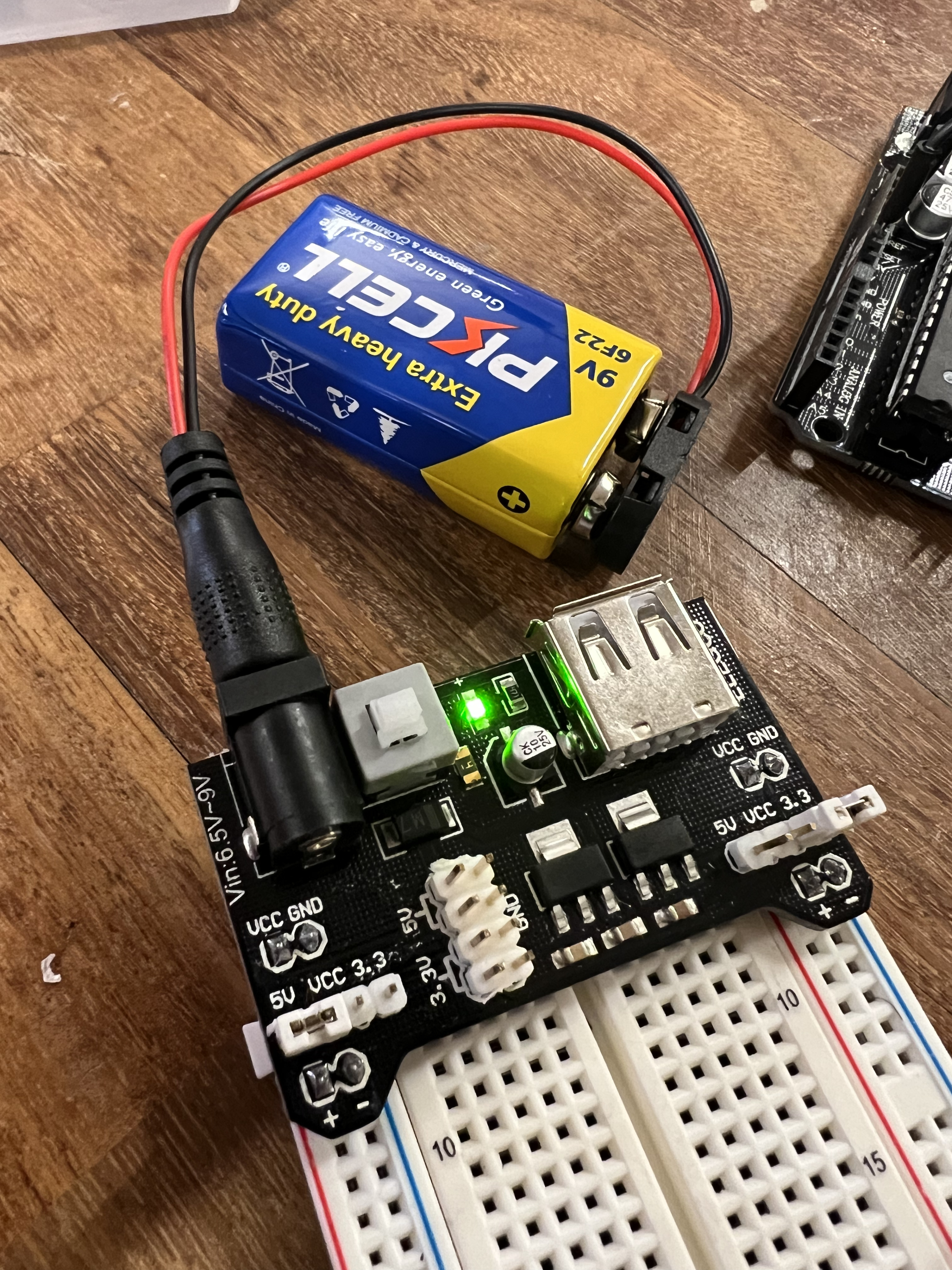
Trying to power motors from the Arduino can burn out the Arduino pins, and sometimes even the USB port on your computer. Therefore, we will be using the 9V battery along with the power supply module from our kit to power the motors we use in this lab.
Refer to Lab 1 and Figure 1 below to refresh your memory about the power supply module, and connect it to your breadboard such that one of the power rails provides the voltage of 5V, and the other provides that of 3.3V.
The only thing we need to make sure is that the ground of the motor power and the ground of the Arduino are connected to each other. However, the 5V from the Arduino should not be connected to the 5V from the power supply module on the breadboard.
Power Set Up
Problems Faced and Conclusion:
I did not have any issues with this part of the lab
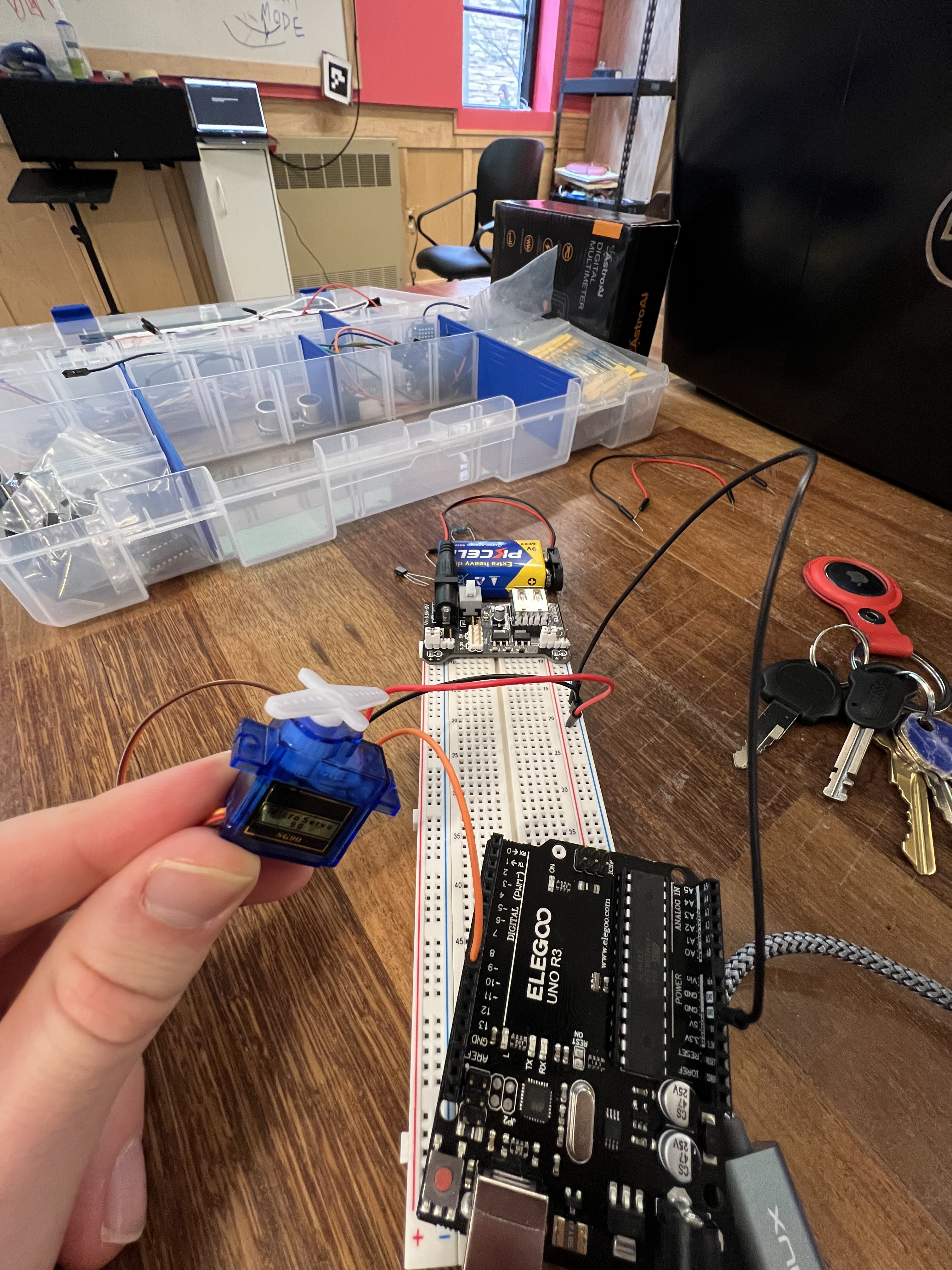
PART 1: WIRING THE SERVO
Procedure:
The servo consists of three wire connections – power or 5V (red), ground (brown), signal (orange/yellow). After we set up the motor power using the power supply module, we can connect the power and ground to the 5V rails.
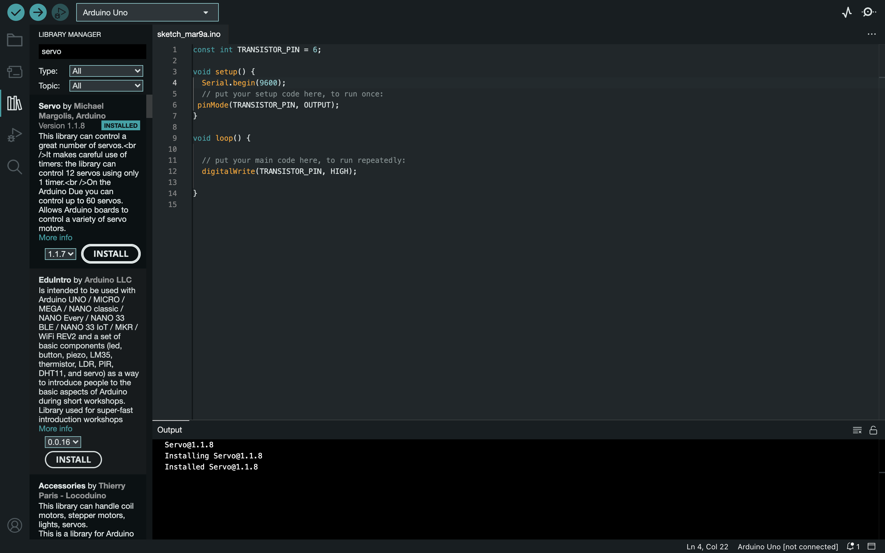
Install Servo.h library in Arduino IDE
Make sure you add one of the servo attachments to the servo shaft (included in the kit) so that it is possible to see the servo rotate.
Follow the code listed below
Servo motor wired
Servo.h Installed
Code for Part 1:
Problems Faced and Conclusion:
I did not have any issues with this part of the lab
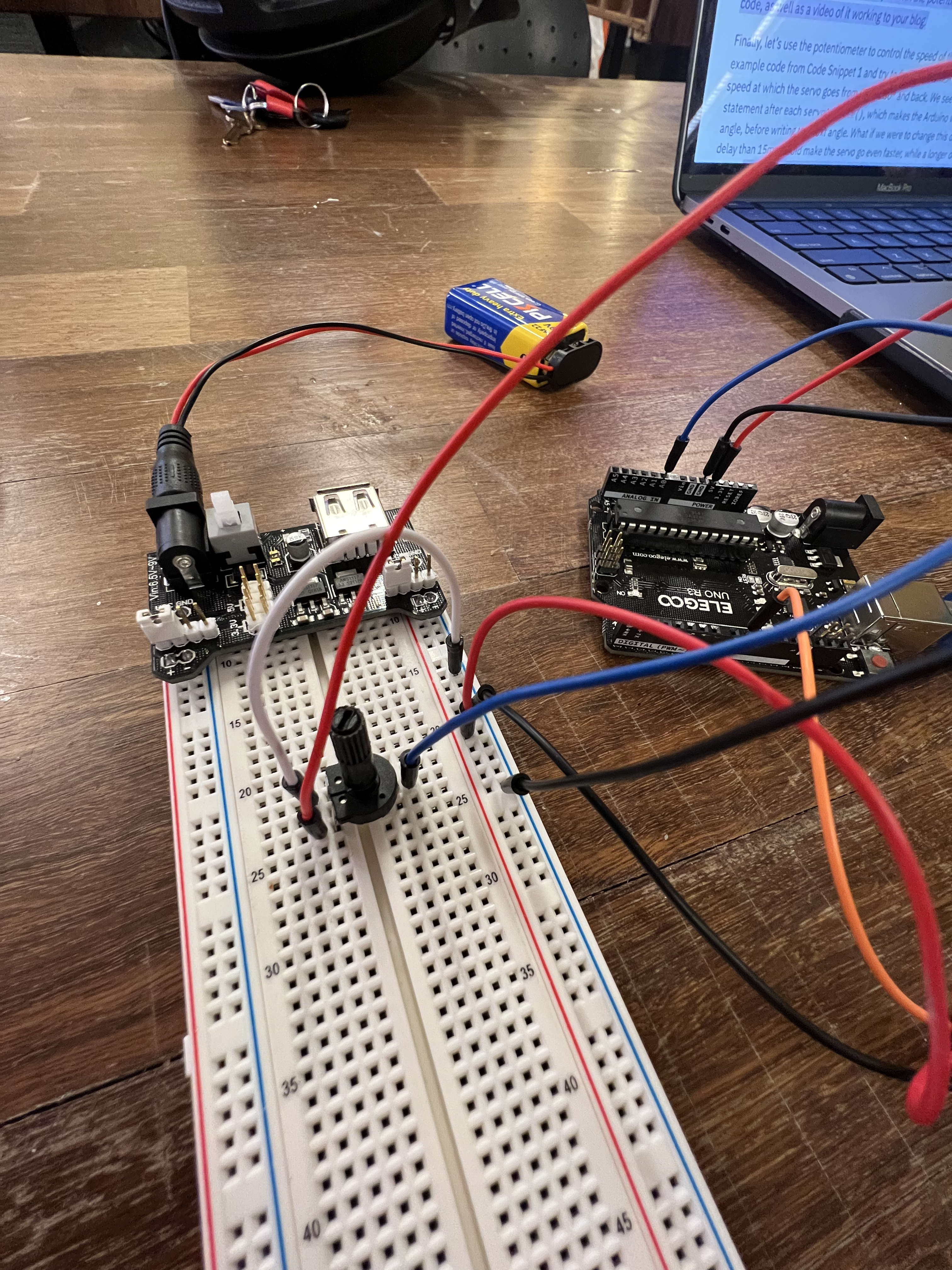
PART 2: CONTROLLING THE SERVO
Procedure:
Similar to how we have been using the potentiometer in the last few labs, connect the potentiometer to the Arduino
Follow the code listed below
Potentiometer wiring:
Code to move the servo in sync with the potentiometer:
Video of servo moving in sync with the potentiometer
Code for delay period changing from 5ms to 50ms based on the input from the potentiometer:
Video of the delay period changing from 5ms to 50ms based on the input from the potentiometer
Problems Faced and Conclusion:
I didn't have any issues for this section of the lab
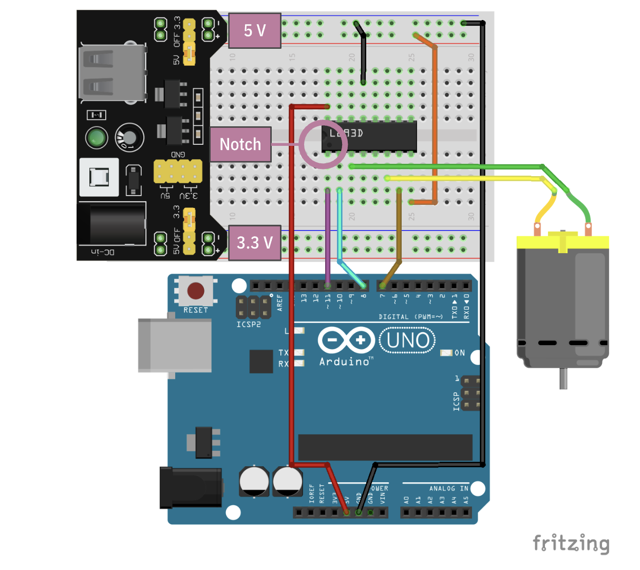
PART 3: DC MOTOR AND MOTOR DRIVER
Procedure:
As discussed earlier, the Arduino should not be used to power the DC motor because of high current requirements, as well as current fluctuations that occur during a motor operation that may be harmful to the Arduino.
Therefore, we use a motor driver, which provides the motors with their own power source, while still allowing control from the Arduino.
Wire the L293D chip according to the schematic provided below
Follow the different samples of code provided to perform the different actions
Picture of the basic fan circuit
Video of basic fan circuit working
Part 3 Schematic
Sample code for fan spinning
Connection of the circuit with the motor driver
Code with the addition of backward() function
Video of forward() and backward() function working
Code for complete sketch with rampUp() and rampDown()
Video of rampUp() and rampDown() function working
Problems Faced and Conclusion:
I had a lot of issues with this section of the lab since my L293D chip kept getting fried and I burnt out 2 of them before I figured out I wasn't being careful enough disconecting the power before messing around with the wiring.
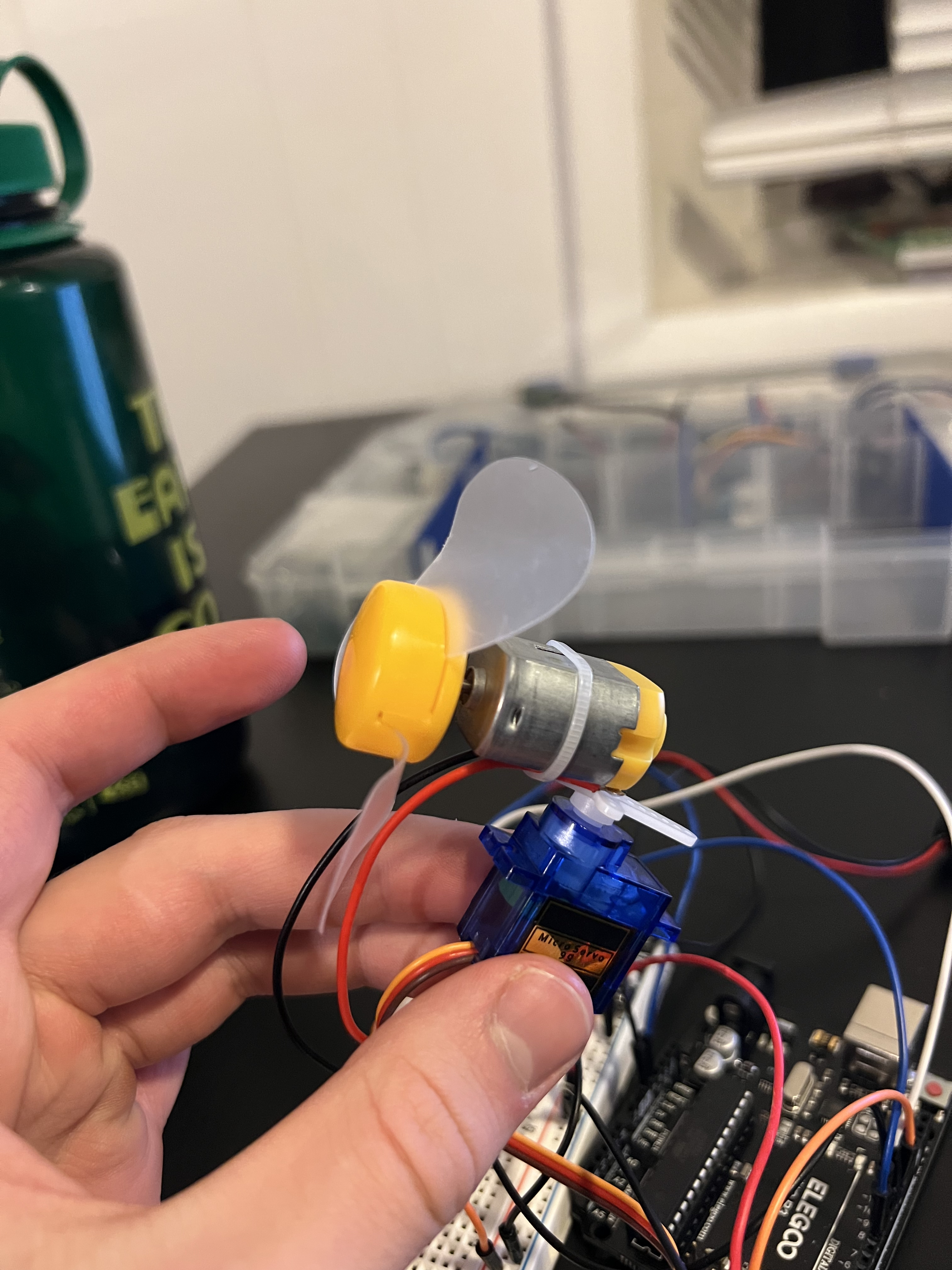
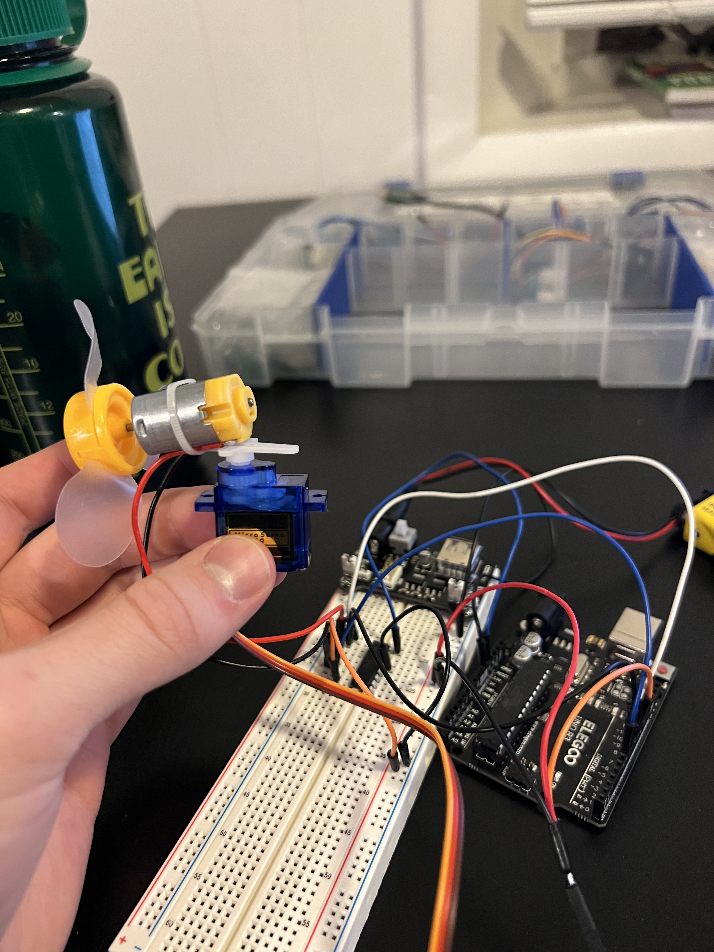
PART 4: TABLE-TOP FAN
Procedure:
Attatch the the motor to the servo
Connect all the components together
Follow the code listed below for making the servo oscillate between 0 and 120 degrees while the fan spins at 70%
Attachment of the DC motor to the servo shaft
Complete circuit with DC motor, servo, and L293D
For the fan to spin at 70% speed we multiply the max output value of 255*0.7 to get 178.5
Part 4 Code:
Video of toy fan working
Problems Faced and Conclusion:
It was a bit hard getting both the servo and the fan to work together but I was able to figure it out fairly easily
Lab 7
Description:
In this lab we will learn how to create interactive animations and visualizations on our computers using Processing, and then connect them to the Arduino to control them using electronics! We learn about Processing and how to use it, and how to set up serial communication between Processing and the Arduino. This is an open-ended lab to allow you to explore the depths of Processing and build something creative and exciting as a practice for your final project!
Materials Used:
Arduino (Elegoo) Uno R3 Controller Board
USB Cable
USB Adapter
Breadboard Jumper Wire
Joystick
Multimeter
PART 0: SETTING UP PROCESSING
Procedure:
Download Processing from Processing.org
Open Processing
Screenshot of Processing Open
Problems Faced and Conclusion:
I didn't face any problems with this section of the lab
PART 1: CREATING WITH PROCESSING
Procedure:
Video of Sample Processing Sketch working
Code for Sample Processing Sketch
Video of modified processing sketch working
Code for Modified Processing Sketch
Problems Faced and Conclusion:
I didn't face any problems with this section of the lab
PART 2: PROCESSING WITH ARDUINO
Procedure:
Connect the joystick module to the Arduino and write a sketch to read its X and Y positions and the state of the push button. To make the push button work, set up the internal pull-up resistor in the Arduino using the pinMode() function call.
Format the values of X, Y, and push button state as a string in a fixed format, for example: "xVal:VALUE;yVal:VALUE;swVal:VALUE;". The X and Y values are analog values between 0-1023, and the push button state is represented as 1 if not pressed and 0 if pressed. Print this string on the serial monitor from the Arduino.
Write a Processing sketch to read the serial data sent from the Arduino and update the animation accordingly. Import the Serial library and create an object to handle serial communication. Use the sample starter code provided to set up the serial communication and use a HashMap to store the received values.
Parse the serial data received from the Arduino using the split() function and update the X and Y positions of the circles and the state of the push button. Use the HashMap to store the received values and retrieve them when needed.
Finally, use the updated values to control the movements of the circles in the Processing sketch. For example, use the X and Y positions to change the position of the circles on the screen, and use the push button state to change their color or size.
Remember that serial communication is one-to-one, so only one application on the computer can communicate with the Arduino at a time. Close the serial monitor when running the Processing sketch or vice versa.
Fritzing Joystick Diagram
Video of Serial Monitor Working
Arduino code for part 2:
Video of Processing Modification Working
Processing code for part 2:
Problems Faced and Conclusion:
Final Project
Executive Summary:
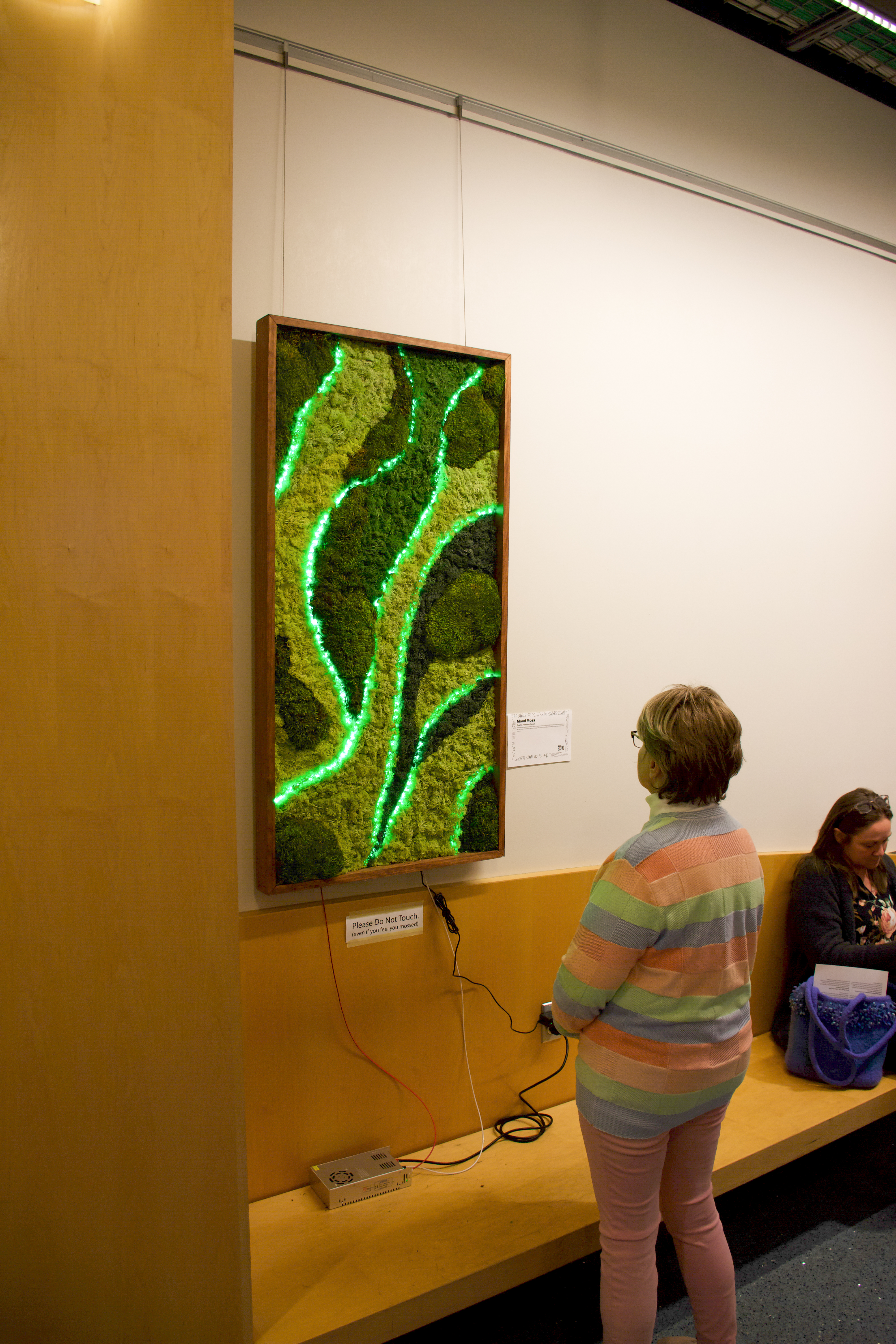
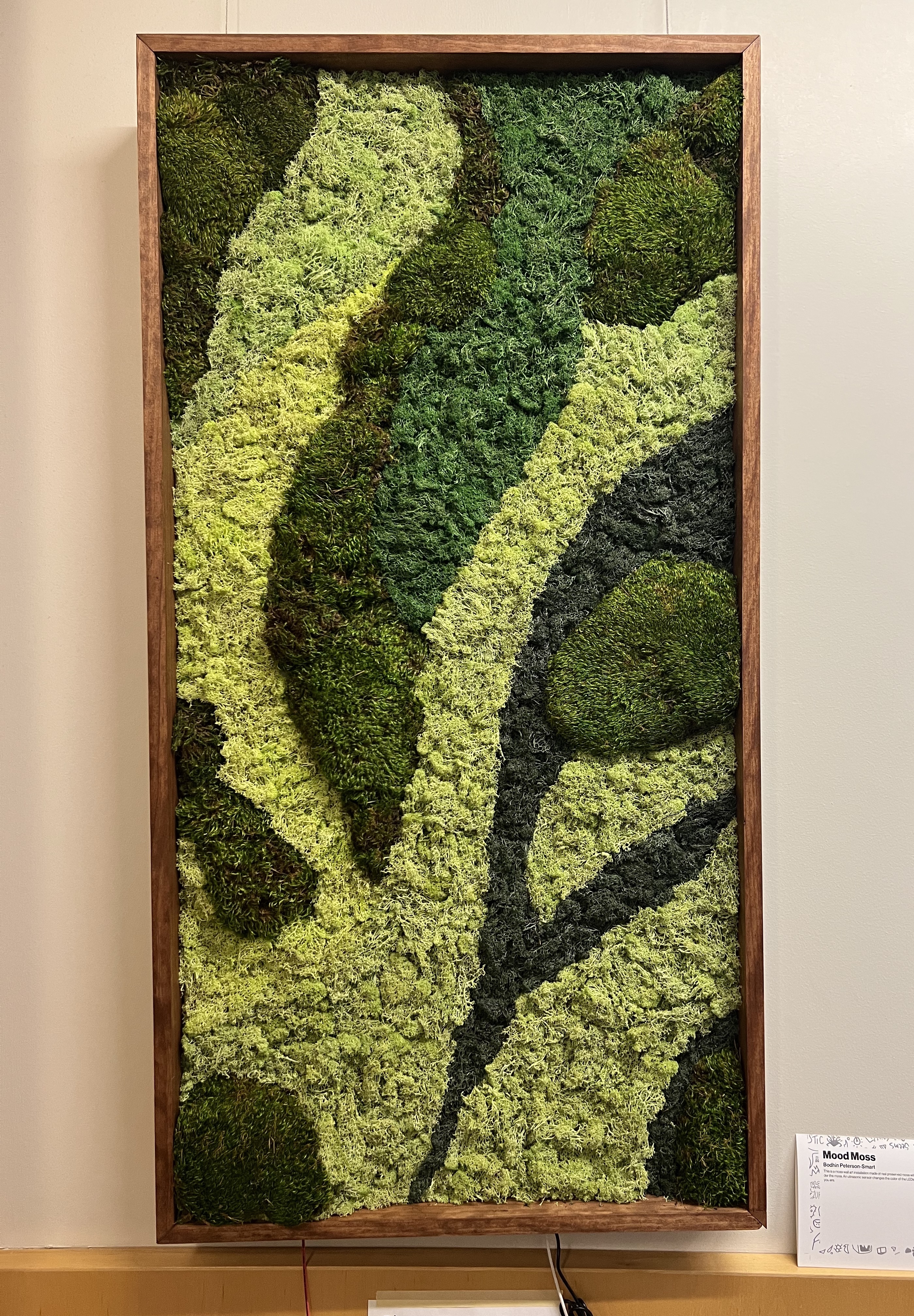
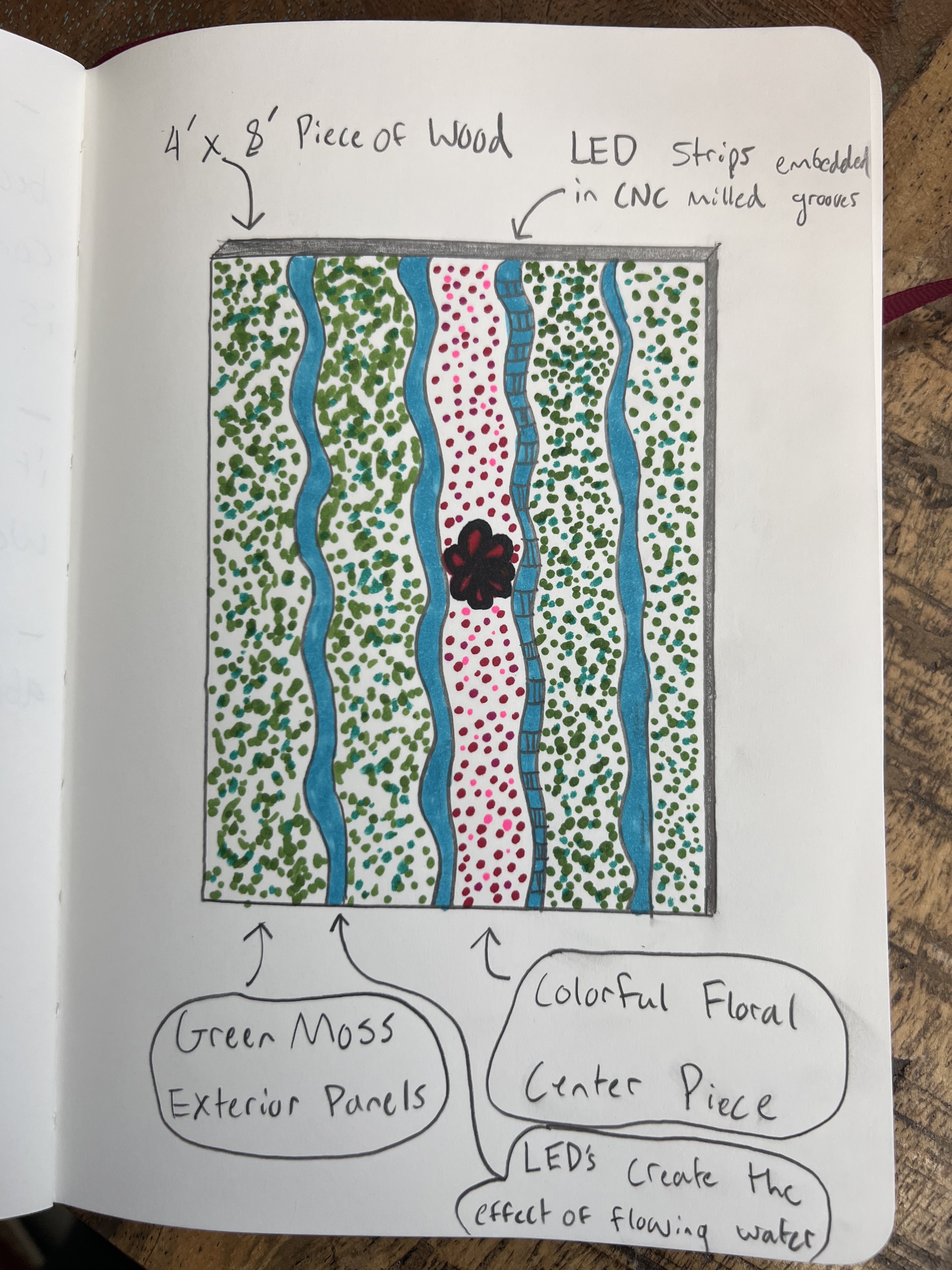
The inspiration for this project came from seeing moss art in various restaurants and buildings in both Boulder and Denver. My desired aesthetic for this project was one of the forest and nature incorporated into technology. The artistic vision behind this project was to develop a unique twist on the moss art I had seen in the past. By embedding LED strips in an almost topographical pattern underneath the moss I was able to create a glowing effect that illuminates the installation. A high priority of mine was to ensure that the LEDs were not visible when they were off and the installation was beautiful with and without the illumination.
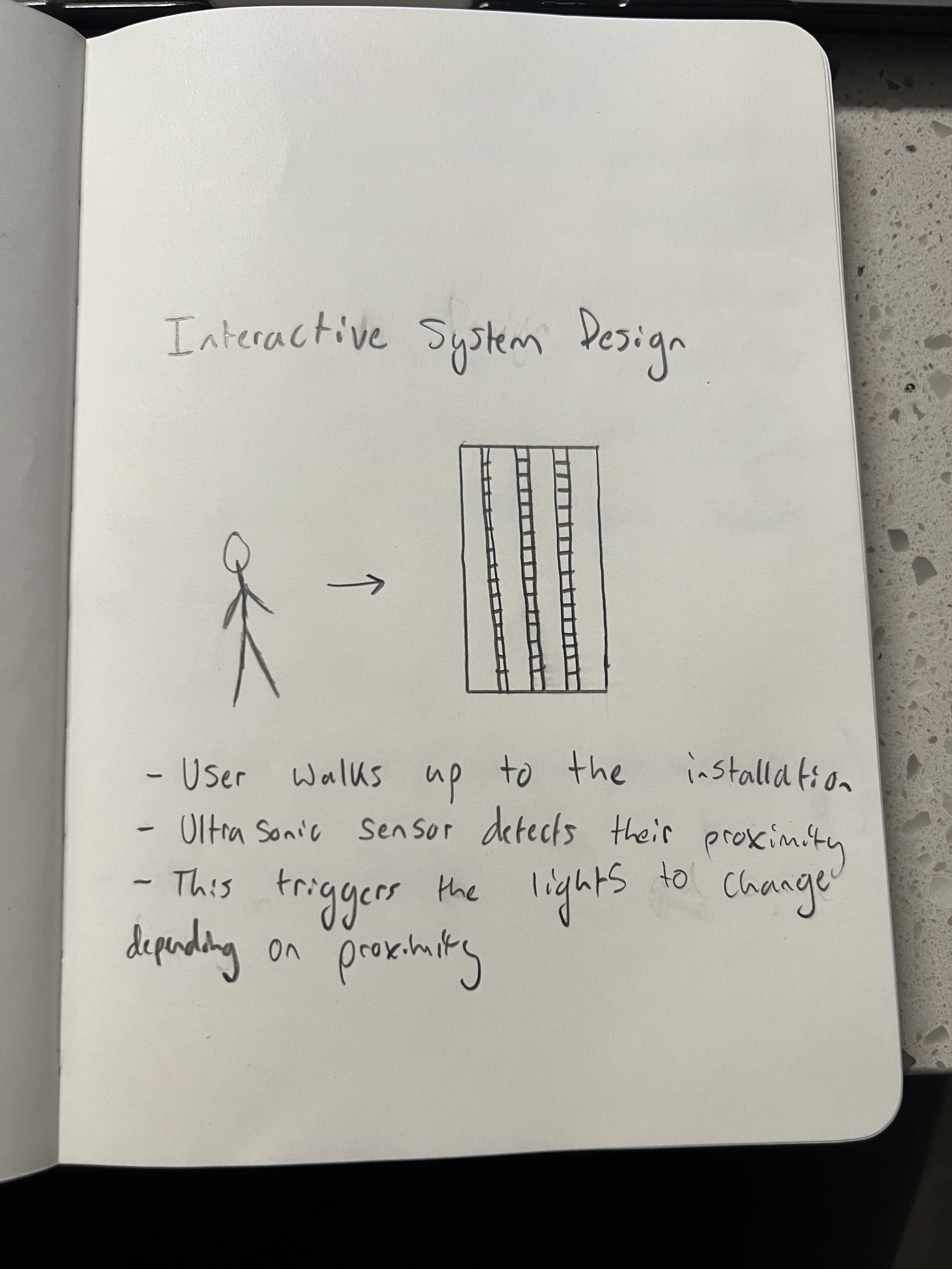
A key component of this installation was the interactivity. My original vision was to have the user walk up to the installation and be greeted with a waterfall-like display of both light and music with the display stopping once the person walked away. Although I liked this initial idea it lacked true interaction and an iterative cycle. The idea I ended up ultimately pursuing was to have the colors of the lights change depending on how close or far the user was from the installation.
To achieve this I used an ultrasonic sensor to detect the proximity of the person viewing the installation and map the values of that sensor to the RBG values of the LEDs. This allows the colors to fade and change depending on the person's proximity. Approaching the interactive component this way was largely successful and although getting the code to work smoothly was a bit of a challenge I am very happy with how the lights turned out.
Presenting this project at the ATLAS Expo along with over 120 other student projects was a rewarding experience and allowed me to see how people interacted with my work. I received lots of positive feedback and praise for the installation which was a nice validation of the extensive hours I put in. It also was good to see that people understood the interaction just by reading the description card. I didn’t want to have something overly complicated that I’d need to explain so I would say I was successful in those intentions.
The process for this project was not linear and I ran into many roadblocks along the way. One of the most disappointing challenges I faced was at the beginning of getting the LEDs set up. I was not being cautious enough with my cable management and I short-circuited one of the LED strips requiring me to start over from scratch. Although this was frustrating it gave me a better understanding of the safety precautions I needed to take to ensure my project was successful and I am grateful that this occurred in the beginning stages and not later on. Some other challenges included incorrectly soldering the DIN pin on one of the LED strips and having to reglue and resolder. Overall this project was an exercise in patience and trusting a long process to come to fruition.
Video Documentation
See executive summary for a detailed explanation of these videos
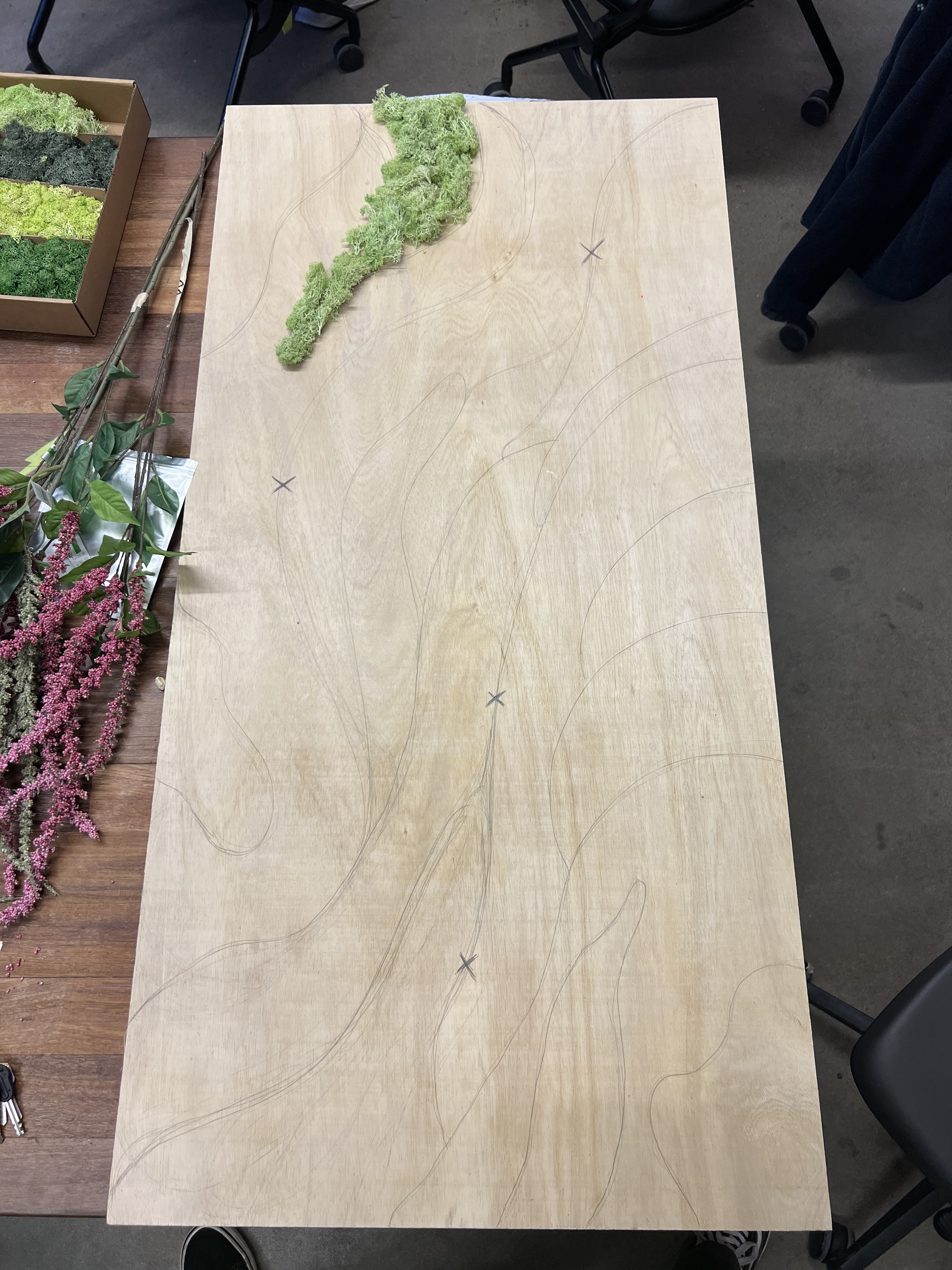
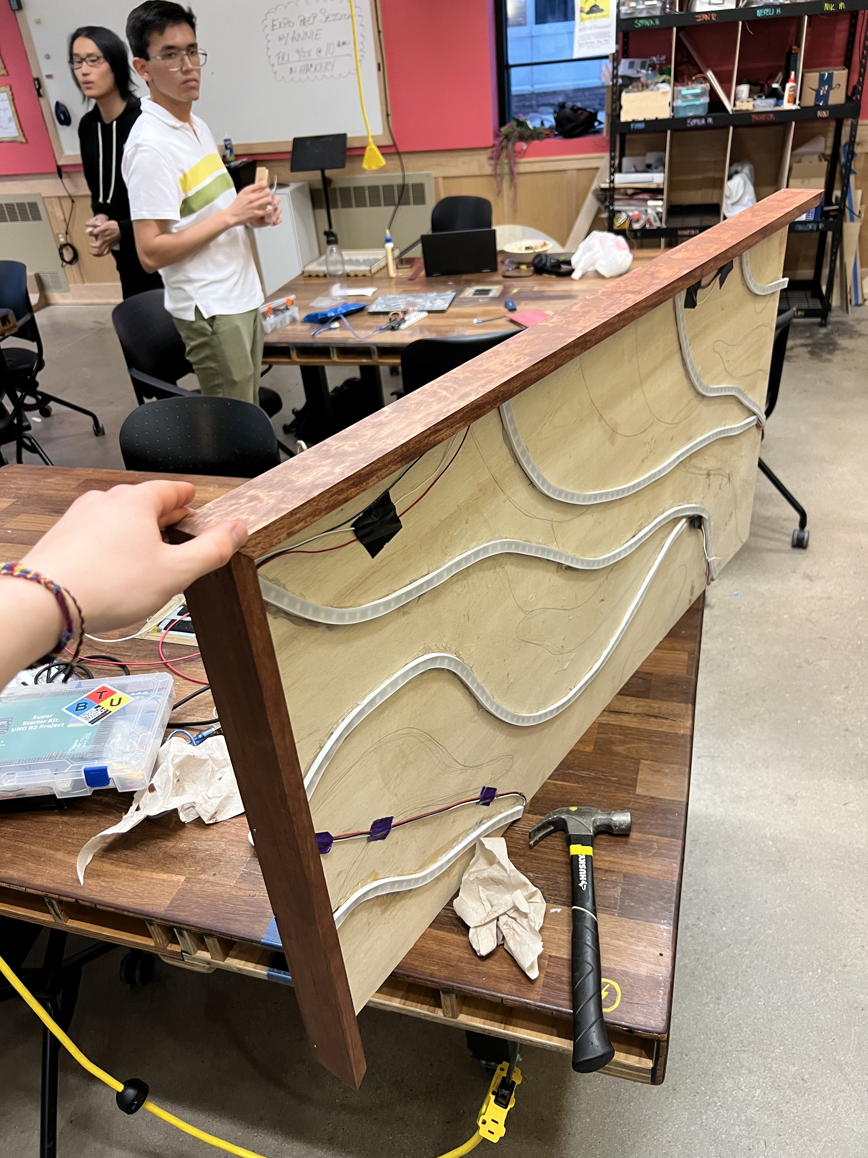
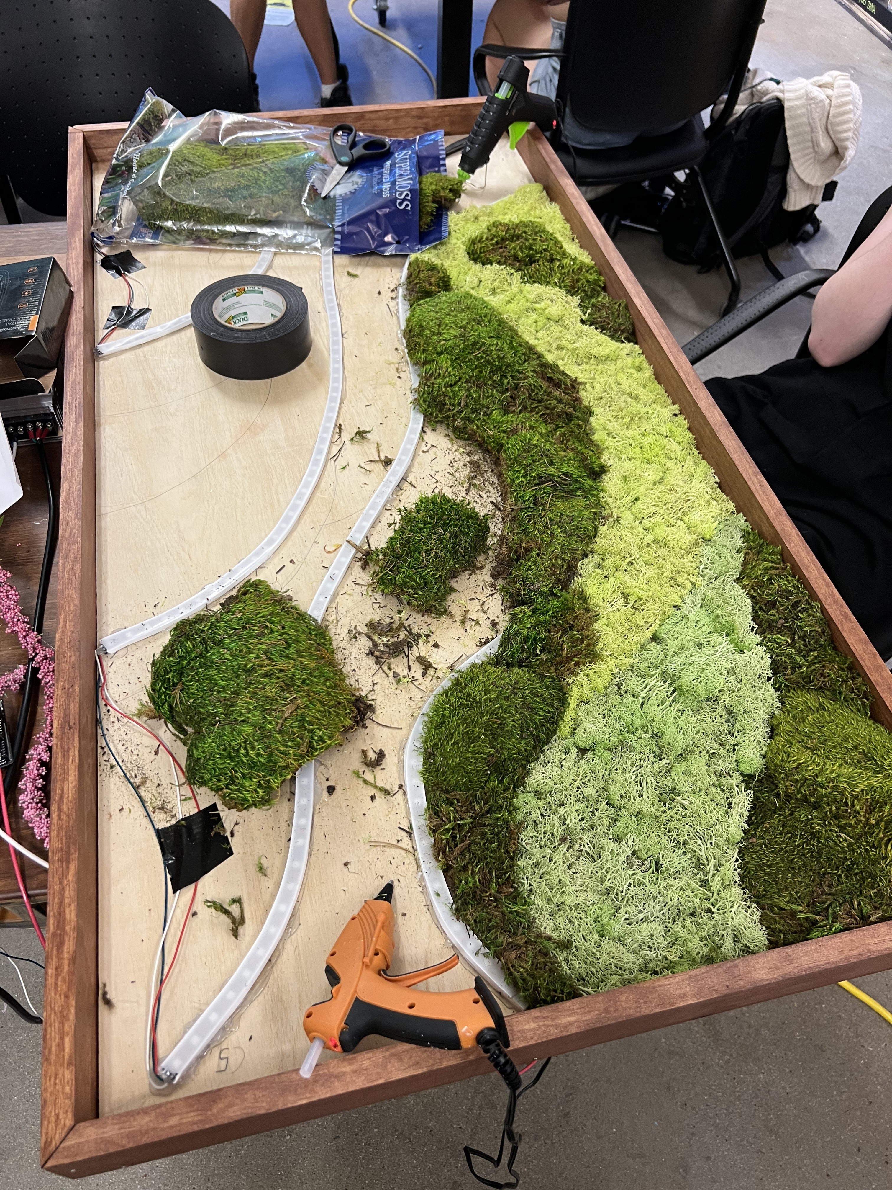
For this initial part of the project I sketched general guidelines for where I was going to have the moss as well as where the LEDs would be marked by the X's
Part 3: Soldering and Gluing LEDs
Process:
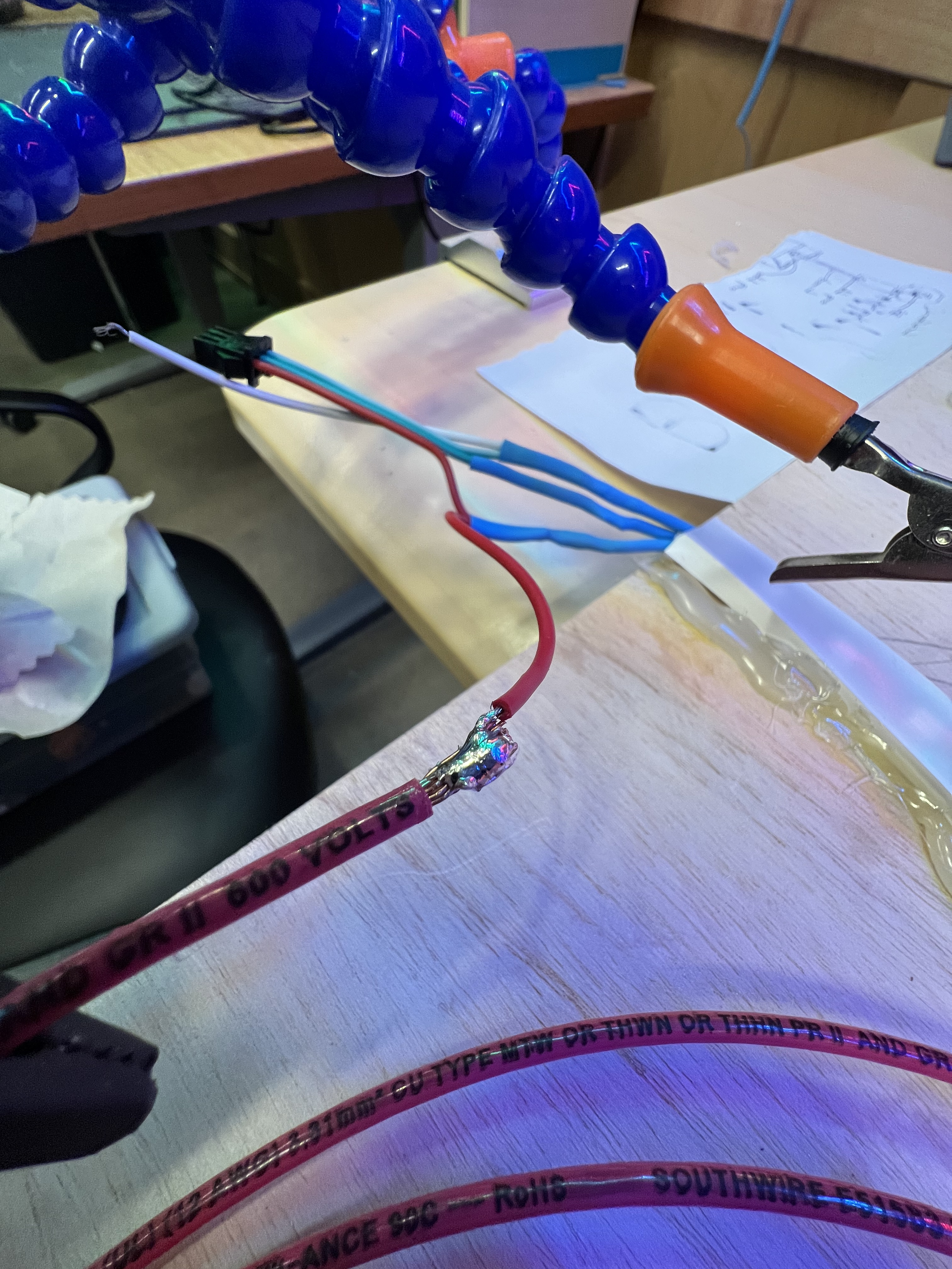
Because I needed to bend the LEDs to create the river effect, I added silicone channels to make it easier to manipulate the LEDs for hot gluing, also diffusing the light. I went through each section marked to have LEDs and cut the strips to length. Soldering for this project was essential because it allowed me to chain the LEDs and space them out throughout the installation while still being connected in series. After each new solder joint, I would use a multimeter to test continuity before adding hot glue to ensure no potential short circuits. I established a color heirarchy having power be red, ground be white, and green be for the PWM pin. This part of the project was by far the most time-consuming and laborious. Having to be very detailed and patient with not only the soldering but also the gluing took up the bulk of the project.
Using hot glue to insulate the solder connections and ensure no short circuits
All of the LEDs glued and soldered together
Part 4: Setting up the power supply module
Process:
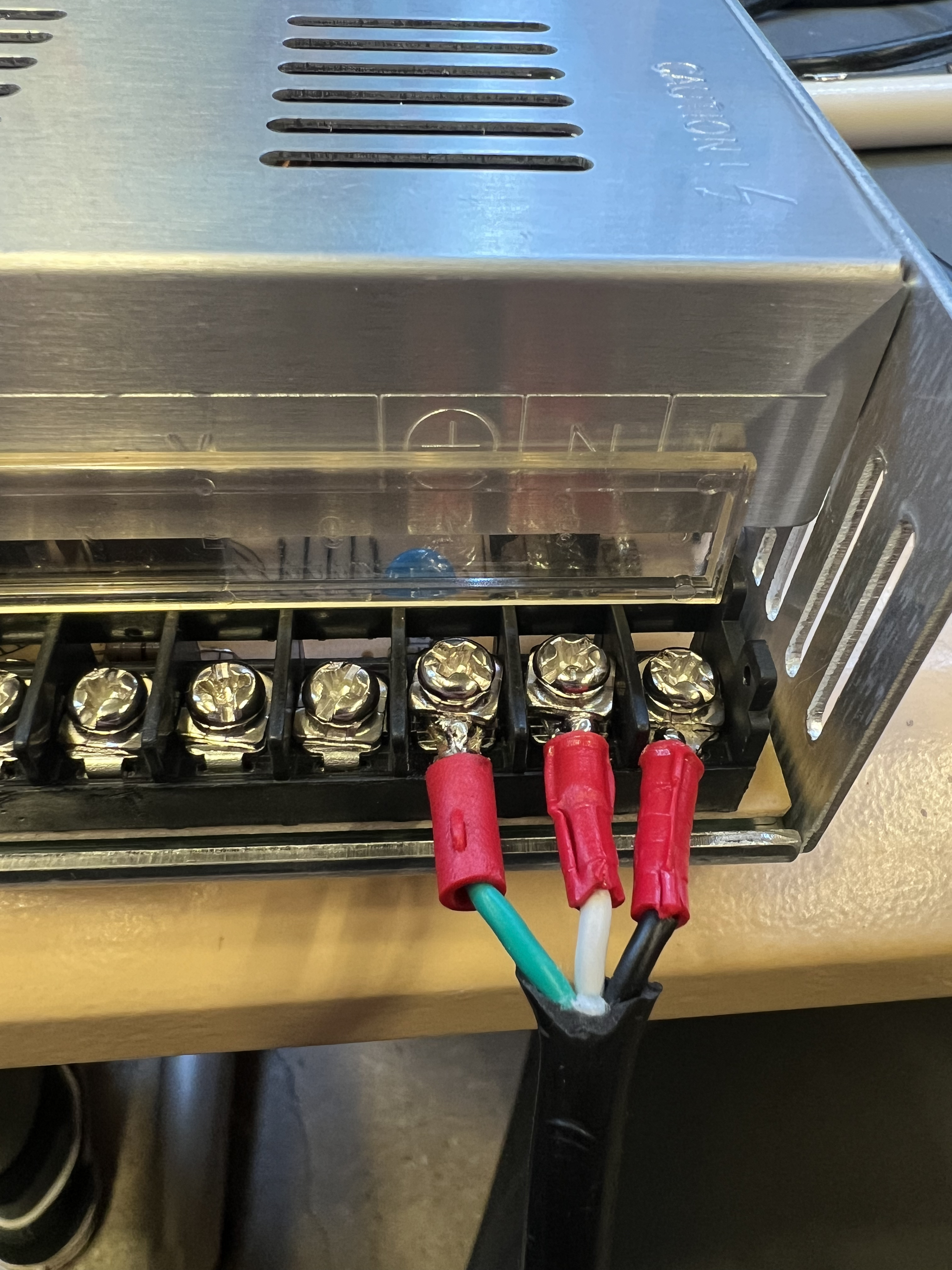
Since this installation consists of 270 LEDs which require 60 mA per LED (16.2 amps total) I purchased a 5V, 60 amp power supply to ensure that the LEDs had enough power. Setting up this power supply, I stripped down an old computer cable, adding crimpable terminals to the wires for extra security. To connect the power cable to the power supply module, you must diligently check the three wires for power, ground, and neutral. I referenced this YouTube video here when setting up these chords as well as testing the different wires with a multimeter since the color coding is sometimes inconsistent. Once the wires are connected to the module correctly, use a multimeter to ensure that 5V is being supplied.
Additionally, to avoid a voltage drop in the long distance between the LEDs/ Power Supply Module, I purchased two 6 ft. strands of 12 gauge wire to solder into the power and ground wires of the LEDs. This size of wire allowed me to add terminals and screw them into the power and ground sections of the supply module. After these steps were complete, I ran some test code to ensure that all the LEDs lit up correctly.
Adding terminals to the power cable
Terminals screwed into the power supply module
Soldering the 12 guage wire into the power for the LEDs
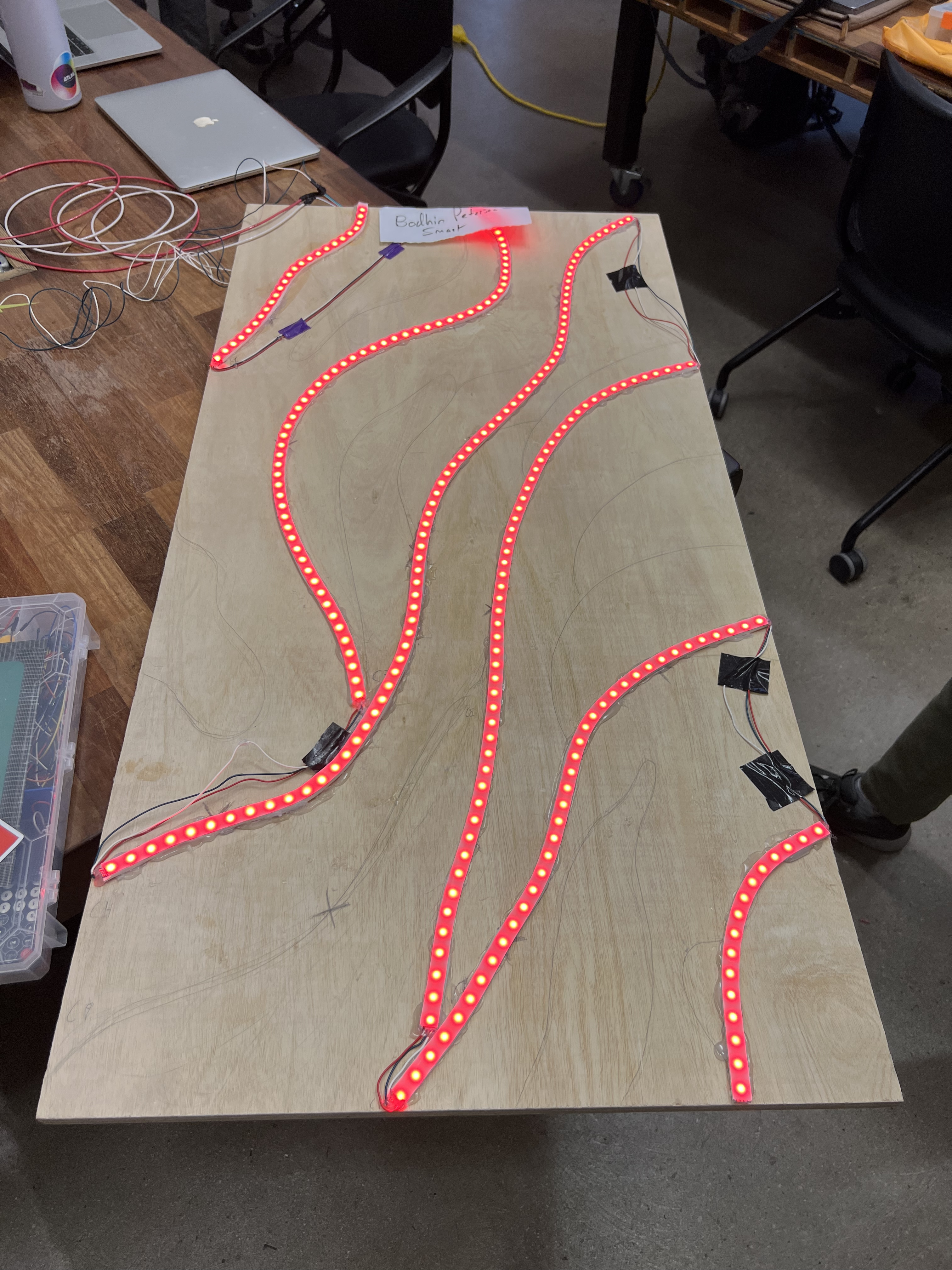
Testing that the LEDs work
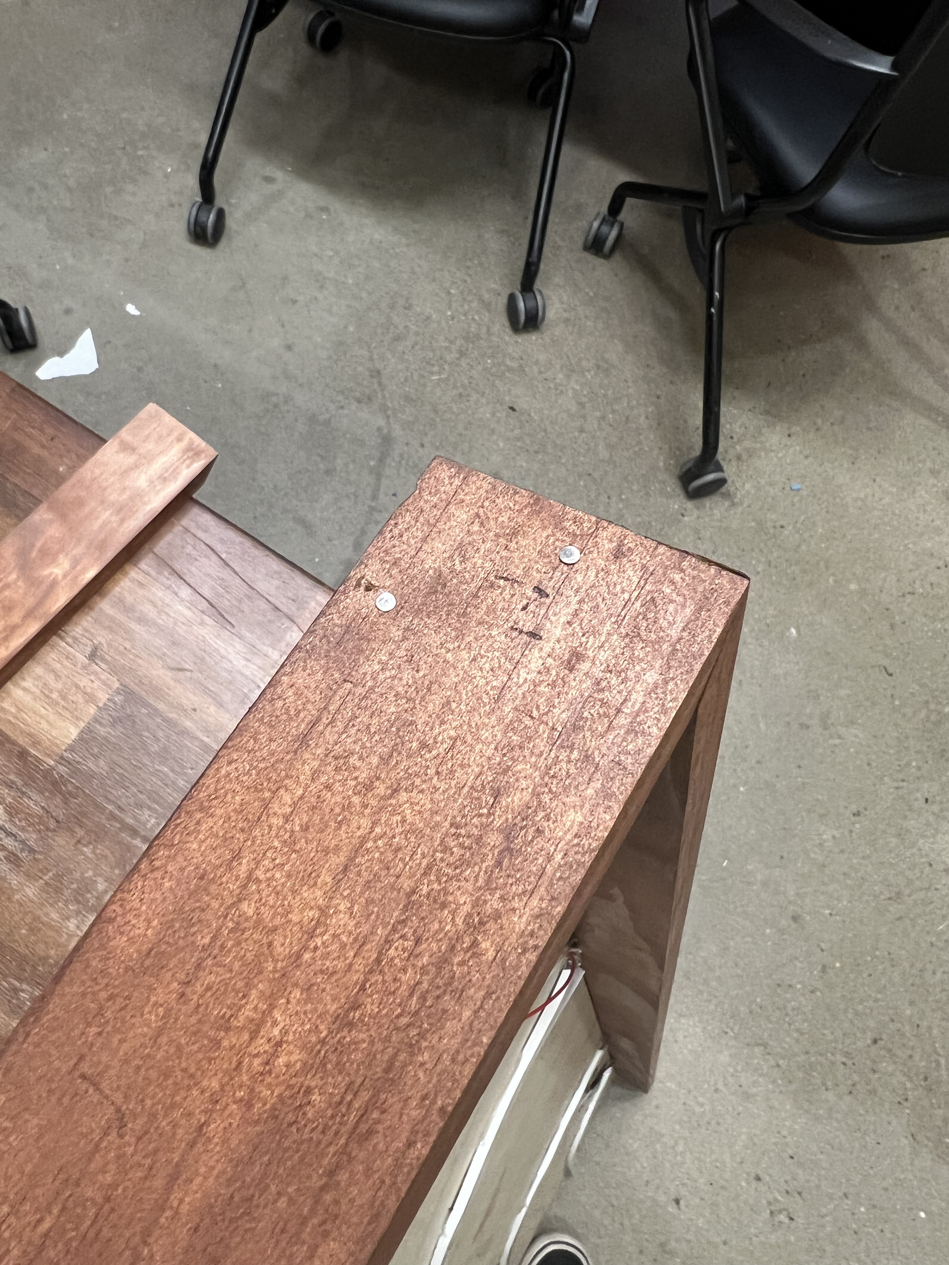
Part 5: Building the Frame
Process:
For this part of the project, I cut the two pieces of 0.75" x 2.5" x 8' pine using a miter saw to create the 45-degree miter joints for the frame.
After the wood had been cut I used the Honey Classic Wood Stain to stain the wood. Once this was completed, I nailed the frame together using #16 x 1-1/2 in. wire nails.
Part 6: Gluing the moss
Gluing the moss was the other very time-consuming part of the project. This took roughly 10 or so hours to complete and required very close attention to detail and planning to achieve the desired outcome.
Part 7: Code/ Arduino Setup
Process
Add FastLED library in Arduino IDE
Follow given code
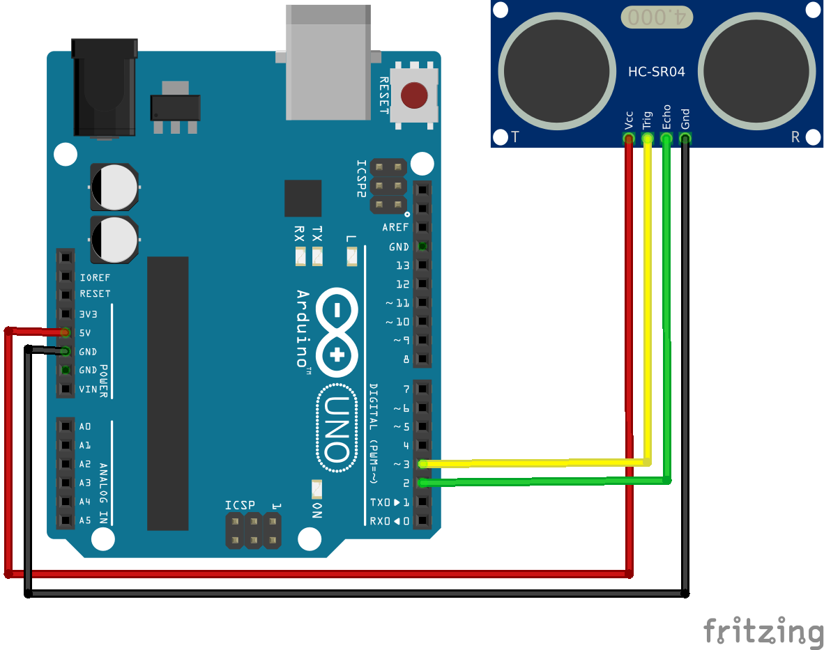
Wiring diagram for the hc-sr04 to arduino
Code for LEDs and hc-sr04 Ultrasonic Sensor
Graphics and Interaction Diagrams
Elements
Text
This is bold and this is strong. This is italic and this is emphasized.
This is superscript text and this is subscript text.
This is underlined and this is code: for (;;) { ... }. Finally, this is a link.
Heading Level 2
Heading Level 3
Heading Level 4
Heading Level 5
Heading Level 6
Blockquote
Fringilla nisl. Donec accumsan interdum nisi, quis tincidunt felis sagittis eget tempus euismod. Vestibulum ante ipsum primis in faucibus vestibulum. Blandit adipiscing eu felis iaculis volutpat ac adipiscing accumsan faucibus. Vestibulum ante ipsum primis in faucibus lorem ipsum dolor sit amet nullam adipiscing eu felis.
Preformatted
i = 0;

while (!deck.isInOrder()) {
    print 'Iteration ' + i;
    deck.shuffle();
    i++;
}

print 'It took ' + i + ' iterations to sort the deck.';